

You are using an out of date browser. It may not display this or other websites correctly.
You should upgrade or use an alternative browser.
You should upgrade or use an alternative browser.
MDA Mk1 with Gulf Arches - Martin P
- Thread starter Martin Potts
- Start date
![Bottle and Pull cables [640x480].JPG](/data/attachments/28/28393-67c4ef3fffcb2a76b253cfe148b568aa.jpg)
![Dash pull cable location [640x480].JPG](/data/attachments/28/28394-0807f0bfe38b644facfb27415f1fa1e6.jpg)
![Exterior Pull Cable 2 [640x480].JPG](/data/attachments/28/28395-e1d94b7489c87643ce09fd71d29eab01.jpg)
Martin,
Do you have any other shots of your pedal box? I am fabricating an accelerator pedal and yours looks interesting. I would swear it has a bell crank in it, but the image isn't clear. My design so far incorporates part of a crank to get the mechanical advantage for the pedal movement. Always collecting ideas.
Bill
Bill, I sent you an Email.
I found a set of suitable E-Marked indicators on my travels today and fitted them. They will hopefully be suitable for the IVA test.
This is my solution.
Martin
I found a set of suitable E-Marked indicators on my travels today and fitted them. They will hopefully be suitable for the IVA test.
This is my solution.
Martin
Attachments
![DSCN3773 [640x480].JPG](/data/attachments/28/28414-34db4f77d8a3a6ec3c3e9793f859b3e1.jpg)
![DSCN3774 [640x480].JPG](/data/attachments/28/28415-fb5a7707cd390416a3ffcf1cc7b5190b.jpg)
![DSCN3775 [640x480].JPG](/data/attachments/28/28416-ce60ee994051e77870bbd5b8f935a4fd.jpg)
![DSCN3776 [640x480].JPG](/data/attachments/28/28417-99a338b7855903904f9a76ab7178133c.jpg)
![DSCN3778 [640x480].JPG](/data/attachments/28/28418-72041f02978257b5bc132e0a13aad8ca.jpg)
I had my panels powder coated along with a mesh grille I made up to go in front of the condensing radiator. Final fitted them this weekend (I'm sure they will come off and on again many times though) and fitted a front towing eye to my front bar assembly. It's not as strong as the rear location but will suffice to winch me off the track or onto a trailor should the need arise.
I'm pleased with the overall fit and finish of the frontal area now and the panelling should function well to direct air onto the radiator. There really is no where for it to go now except through the rad. I fitted seals everywhere where I could see a gap.
It's difficult to get a good photo of the panelling and details now as everything is black and it all blends into the background which is exactly what I wanted. leased:
I'm pleased with the overall fit and finish of the frontal area now and the panelling should function well to direct air onto the radiator. There really is no where for it to go now except through the rad. I fitted seals everywhere where I could see a gap.
It's difficult to get a good photo of the panelling and details now as everything is black and it all blends into the background which is exactly what I wanted.
leased:Attachments
![DSCN3810 [640x480].JPG](/data/attachments/28/28893-cc901bb4343e59ec3fde1a04ba5b3d87.jpg)
![DSCN3809 [640x480].JPG](/data/attachments/28/28894-19bc9b6d12aa86e5844f06d929a9ea75.jpg)
![DSCN3812 [640x480].JPG](/data/attachments/28/28895-0c7a3d57983cb079dd1c1c47bf932ba7.jpg)
Back from the Stoneleigh KIt Car Show and fitted the bits I picked up. (Starter button, Hazard switch and 12V auxilliary socket). The Dash layout is now finalized in my mind, so I fitted everything in. The Heater and air con controls will be on a separate panel on the bottom of the dash.
Met some guys from the forum at the show, Martin Gough, Steve Barker, Tony Hunt, John Oxborough, Alastair Ward, all great guys and a real pleasure to mix with.
Martin
Met some guys from the forum at the show, Martin Gough, Steve Barker, Tony Hunt, John Oxborough, Alastair Ward, all great guys and a real pleasure to mix with.
Martin
Attachments
![DSCN3815 [640x480].JPG](/data/attachments/28/28903-3f6ee3368edd24eb1692c1a30cfe4886.jpg)
![DSCN3816 [640x480].JPG](/data/attachments/28/28904-5636e41bbf55a3e3d878d652e43f0c95.jpg)
![DSCN3817 [640x480].JPG](/data/attachments/28/28905-608576de3aa8d67af8ded823f74ab1d7.jpg)
Today fitted the heater pipes in the front to the evaporator unit routing them inside the car and fixing with P-Clips and tie wraps. Also started to make up the air con hoses.
Martin
Martin
Attachments
![DSCN3806 [640x480].JPG](/data/attachments/28/28906-b9fe3128880f4838df348593a281da52.jpg)
![DSCN3807 [640x480].JPG](/data/attachments/28/28907-318848454016a7785ac5670a428bb3de.jpg)
![DSCN3808 [640x480].JPG](/data/attachments/28/28908-6e87ac30caded96f8e2e0d16c683d5e0.jpg)
![DSCN3804 [640x480].JPG](/data/attachments/28/28909-6c98e6883ed96d3e65c2ea5c953a0276.jpg)
![DSCN3805 [640x480].JPG](/data/attachments/28/28910-87c1dc7d4473209dc3aec501ee6ad851.jpg)
Martin,
I too have a start button. Mine came from a Honda S2000. I down loaded the wiring diagram for it to make it work. It is something you might be interested in. It allows for a safety factor in that it uses a brake switch in the hydraulic line for the clutch that ultimately controls the ground for the switch. That way you can't start the engine til the clutch is depressed.
Bill
Hi Martin ....I have been checking out your build and as with all the guys on here yours is up to the mark. I have noticed that you all have fire systems in your cars be they track or road cars (very wise) but looking at yours it easy to see how it operates etc my question (concern) is that you would have to remove the pin from the unit before you could use it. Not a problem at the track, but what about when driving on the road?? My concern would be some little delight pulling the out side activator while you were in having a coffee. Of course you could leave the pin in while in road use but then you don't really have a working system. You may have some fail safe device to avoid this that I can't see. Cheers Leon
Hi Dave,
Nice to hear from you. Hope the move to Canada is going well.
Bill,
I have a wiring diagram for the switch but it has no fail safe like yours. I really like the idea and would be very interested to see the wiring diagram you have. Thanks a lot.
Leonmac,
You are spot on and I appreciate you taking an interest. Mine is indeed a very simple system. The Mechanical system I have was installed for track use and therefore the pin will be removed. For road use I will have a hand held inside the car and the mechanical system will not be operational. As I have an exterior pull T I, it would be too easy for some idiot to pull it if I left the pin out permanantly. Of coarse I have the option on long journeys to take the pin out and have it operable before I leave the house, then put the pin back when I arrive at my destination. Not a big deal I think. My logic was better to have one than not, even if it is a little compromised in certain situations.
Martin
Blimey! Is that Hampshire? I though it was Surrey :laugh:
Regretfully, I am exactly 58 miles South of you.. I was hoping to stop by and view your magnificent build, but it's a wee bit far for a 'pop around'. Never mind, one day....
Fantastic bit of work from your pictures.. Keep it up mate.
Regretfully, I am exactly 58 miles South of you.. I was hoping to stop by and view your magnificent build, but it's a wee bit far for a 'pop around'. Never mind, one day....
Fantastic bit of work from your pictures.. Keep it up mate.
Last edited:
Martin,
Here is the diagram for reference.
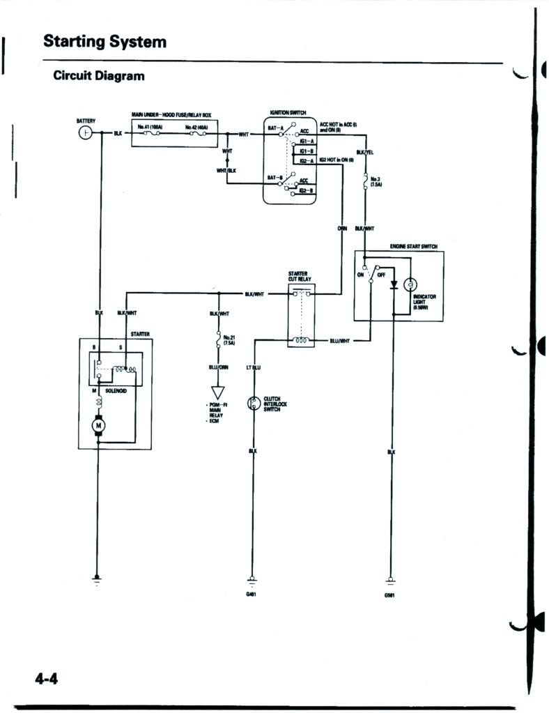
Yours will undoubtedly be different. If you think about it, the button is nothing more than a relay or controlling a relay(solenoid). Here is a pic of an average relay. You can buy packs of them on ebay or any electrical outlet for a few bucks.

If your button is just a ground wire, just add the brake switch to the clutch hydraulic line and run the ground wire to it and to a suitable ground.
If the button is a true relay the big power wire to the starter goes IN to the relay. The big OUT line goes to the starter. In this pic it is the red and yellow wires. It doesn't matter which you choose. There is a little wire that controls the switch/magnet in the relay that will allow the power to go to the starter(white and black). It can come from any low amp source. 5 or so from a switched source(on when key is turned on, off when off).The small wire OUT(usually the black wire) is the ground wire. Once it is grounded(your pushing it) it allows the power to go to the starter and turn it over.
All you have to do is add a brake switch to the clutch hydraulics line and run the ground wire to one side and the other to a suitable ground source. Once the clutch is pushed in, and the button pushed, it will complete the circuit and the starter turns. Relays can be used for many functions to turn things on(alarm system) or turn them off(running water pumps and fans after ignition is off), or controlling other relays. With my car I have 10-12 relays to control the various fans(4) pumps(4) and other big power items. So I have two relays that supply just the power to the relays so they can function.
If you need education on relays, Google "electrical relay" or read about them here:
BASIC ELECTRICITY TUTORIAL - RELAYS
Bill
Here is the diagram for reference.
Yours will undoubtedly be different. If you think about it, the button is nothing more than a relay or controlling a relay(solenoid). Here is a pic of an average relay. You can buy packs of them on ebay or any electrical outlet for a few bucks.
If your button is just a ground wire, just add the brake switch to the clutch hydraulic line and run the ground wire to it and to a suitable ground.
If the button is a true relay the big power wire to the starter goes IN to the relay. The big OUT line goes to the starter. In this pic it is the red and yellow wires. It doesn't matter which you choose. There is a little wire that controls the switch/magnet in the relay that will allow the power to go to the starter(white and black). It can come from any low amp source. 5 or so from a switched source(on when key is turned on, off when off).The small wire OUT(usually the black wire) is the ground wire. Once it is grounded(your pushing it) it allows the power to go to the starter and turn it over.
All you have to do is add a brake switch to the clutch hydraulics line and run the ground wire to one side and the other to a suitable ground source. Once the clutch is pushed in, and the button pushed, it will complete the circuit and the starter turns. Relays can be used for many functions to turn things on(alarm system) or turn them off(running water pumps and fans after ignition is off), or controlling other relays. With my car I have 10-12 relays to control the various fans(4) pumps(4) and other big power items. So I have two relays that supply just the power to the relays so they can function.
If you need education on relays, Google "electrical relay" or read about them here:
BASIC ELECTRICITY TUTORIAL - RELAYS
Bill
Last edited:
Thanks Bill, really usefull stuff.
I put in my interior light assembly today. I took a while deciding on one. I picked this one in the end due to the shape, as its profile follows the line of the windscreen and is discretely tucked up in front of the roll cage. It's a modern add on I know, but as a street car I need a few mod cons.
Martin
Attachments
![DSCN3818 [640x480].JPG](/data/attachments/29/29094-15670ad7fd987c95c3ee049ccd2ddb51.jpg)
Kieth/Martin. I was having alittle chuckle to my self reading your post about catching up and seeing Martins car. Its funny how different people in different countries percieve distance. Keith made the comment that 58 miles was a great distance where as in NZ we travel that far to work every day and would think nothing of going that far for a day at the beach or just for a visit with friends, My brother live in Australia and they would think nothing of driving further than that for a hamburger. not a critisium, just an interesting observation. sorry for the thread drift. Leonmac
Agreed Leon, I was shocked to hear that my cousin in Canada would drive a round trip of 40 minutes to go through a particular drive through just for a coffee. In a Suburban! That must make it $50 a slurp! Just as well her husband is in the oil business.
Sorry Martin diverting your thread, better bring it back on track......
Hey Martin, still see you are adding weight, mighty heavy looking interior light you have there mate! Actually, interesting position you have chosen for it at the front of the roof. Did you consider putting it on the rear bulkhead? Really easy to wire in if there.
Hi Malcolm,
I have been fabricating a rear drip tray for my roof vent that sits behind my head, so it can't go there. I chose the forward location for ease of use. Reaching behind you for anything is more of a pain and it really is easy to reach in this location and the light will fall on your lap which is where you want it, so I think I've got it right. Apart from the extra weight of coarse.
Martin
I took another look at my rear ducting and realised that the ducts were not really directing the air where it needed to go so I completely reprofiled the ends of the ducts to direct the air to the brakes more effectively.
Martin
Martin
Attachments
![DSCN3825 [640x480].JPG](/data/attachments/29/29114-d246f82460194d15d1579add2cc62641.jpg)
![DSCN3826 [640x480].JPG](/data/attachments/29/29115-baab343d879433f3044e621e285e8c2a.jpg)
![DSCN3828 [640x480].JPG](/data/attachments/29/29116-2206e9757f93bb384655bec1edf06f75.jpg)
Similar threads
- Replies
- 4
- Views
- 6K
- Replies
- 1
- Views
- 4K
- Replies
- 12
- Views
- 3K