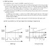
Toyota have begun using MRE (Magnetic Resistance Element) sensors in their 2007 engines. These things are like a cross between VR (mag pickup) and Hall sensors, and they're really slick because they produce a crisp square wave output regardless of RPM, like a Hall sensor, but they operate from a simple toothed gear and don't require the rare earth magnets to be embedded in the gear as a Hall does.
Seems like they'd be a perfect swap-out for VR (mag pickup) type sensors. And with their RPM independent, clean square wave output, they should offer some real improvement for stabilising timing in EFI systems.
Denso, the manufacturer, has this to say about them:
Benefits and Features (MRE Type)
Seems like they'd be a perfect swap-out for VR (mag pickup) type sensors. And with their RPM independent, clean square wave output, they should offer some real improvement for stabilising timing in EFI systems.
Denso, the manufacturer, has this to say about them:
Benefits and Features (MRE Type)
- High detection accuracy
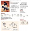
- DENSO’s cam/crank position sensors use a unique arrangement of two pair of MREs on an IC chip, achieving high detection accuracy, including just after the engine starts. The MRE cam/crank position sensors have almost 10 times higher sensitivity than Hall element cam/crank position sensors.
- In DENSO’s MRE cam/crank position sensor, the molded IC chip is installed inside a cylindrical magnet, which means the IC chip is positioned closer to rotor gears rotating with the cam or crank shaft, providing even higher sensitivity.
- High reliability
- The molded IC chip and the cylindrical magnet are integrally covered with poly phenylene sulfide(PPS) resin for greater strength.
- PPS resin has high resistance to chemical substances including fuel, engine oil and emissions