Since I am basically snowed in, and recently got acces to a CFD package, I thought I would do a little investigation into the inlet side of everyones favorite form of fuell addition, the webber carb.
CFD stands for Computational Fluid Dynamics, or as one of my proffessors likes to call it, Colorful Fluid Dynamics, because of the pretty pictures it generates. Basically CFD is a way to simulate fluid flow. This can be internal flow, like in pipes, junctions, etc., or can be external flow, like around a car body (hmmm, possible future topic?).
What we are going to investigate is the effect of runner inlet geometry on flow. I have chosen this because it is a very simple case that doesn't require much computer power.
For our baseline case, we are going to look at a simple pipe pulling air from ambient. This could be an inlet pipe sticking way out of a wall into an empty room, or a webber carb with a really crappy velocity stack on it.
In our model, we are flowing air at standard temperature and pressure. We are applying a static pressure difference if 28 inH2O across our test piece. The test piece is 2" wide and 40" long. I know from experience that it takes a length of about 20 tube diameters for flow to become fully developed in a straight duct. This is important because we want to measure the total losses realized due to the inlet geometry. If we were to use a tube only 10" long, we would not be accurately measuring the losses due to the inlet. Of course no engine in the world has runners that are perfectly straight and 20 diameters long. We just want to accurately quantify the effects of the inlet. Anyway, on we go.
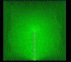
Below is the mesh used to simulate the pipe sticking into ambient. All the green lines show the cells that the area is broken up into. Generaly speaking, the more cells, the more accurate the result. If you squint, you can see the pipe walls in white. Don't wory, it will be more clear in the next picture.
CFD stands for Computational Fluid Dynamics, or as one of my proffessors likes to call it, Colorful Fluid Dynamics, because of the pretty pictures it generates. Basically CFD is a way to simulate fluid flow. This can be internal flow, like in pipes, junctions, etc., or can be external flow, like around a car body (hmmm, possible future topic?).
What we are going to investigate is the effect of runner inlet geometry on flow. I have chosen this because it is a very simple case that doesn't require much computer power.
For our baseline case, we are going to look at a simple pipe pulling air from ambient. This could be an inlet pipe sticking way out of a wall into an empty room, or a webber carb with a really crappy velocity stack on it.
In our model, we are flowing air at standard temperature and pressure. We are applying a static pressure difference if 28 inH2O across our test piece. The test piece is 2" wide and 40" long. I know from experience that it takes a length of about 20 tube diameters for flow to become fully developed in a straight duct. This is important because we want to measure the total losses realized due to the inlet geometry. If we were to use a tube only 10" long, we would not be accurately measuring the losses due to the inlet. Of course no engine in the world has runners that are perfectly straight and 20 diameters long. We just want to accurately quantify the effects of the inlet. Anyway, on we go.
Below is the mesh used to simulate the pipe sticking into ambient. All the green lines show the cells that the area is broken up into. Generaly speaking, the more cells, the more accurate the result. If you squint, you can see the pipe walls in white. Don't wory, it will be more clear in the next picture.