

You are using an out of date browser. It may not display this or other websites correctly.
You should upgrade or use an alternative browser.
You should upgrade or use an alternative browser.
What would you do?
- Thread starter llarsen
- Start date
Lynn Larsen
Lynn Larsen
John Ross,
Hmmmm...............Now I am questioning the accuracy of the alignment. Here are the settings we were shooting for (settings provided by John Donnelley):
Ride height: 4.5" front 5.0" rear
FRONT
Camber: -0.5°
Caster: +4°
Toe-In: 1/8" (30 minutes)
REAR
Camber: -.75°
Caster: 0
Toe-In: 1/16" per side (1/8" total)
I ended up with the following settings with the alignment:
Camber: Left -0.2° Right -0.4°
Caster: Left 4.8° Right 4.8°
Toe : Left 0.05" Right 0.05"
I don't recall the process we followed, but I will follow this procedure next time:
After setting the ride height you want, set Toe as close to 0 as you can get. The lower A arm and ball joint have no adjustment and, therefore, are in a fixed position. Start with upper A arm in the most forward position possible and the rod end threaded in (short) as far as the jam nut will allow. I am assuming the camber will be something less than the desired -0.5° and the caster will be something less than the desired +4°. Extend the rod end, which will add camber and caster, until one or the other is very close to the desired value. Toe adjustments will affect caster and camber, so it would probably be a good idea to try to get it close to the desired setting at this time. If both caster and camber have gone too positive with the toe change, shorten the rod end 1/2 revolution at a time until one is very close to the desired setting and the other is just on the negative side of its target. Now add one shim in front of the upper A arm inner mounts (and remove one from behind them.) This will add both camber and caster, but at a different rate than rotating the rod end. From here, you will be chasing the desired values by next adjusting the rod end and then checking the toe. Repeat iterations of this cycle until values are as close to desired as you can get them.
This should end up with the rod end extended as far as possible and, hopefully, it will be extended enough to allow for the jam nut to be in place.
It might be that I achieved the desired settings by means of moving the upper A arm back too much which would have to be off set by shortening the rod end, which ended up with the rod end so short that the jam nut won't fit.
Lynn
Last edited:
I would very seriously suggest that if indeed you will have to have new arms made, or heavily modify the ones you have, that you just have new ones with a better design made. By moving that upper rod end, you are changing camber, castor, toe, AND bump steer. If I had to set a car up with an adjustment like that I think I would end up throwing a tool through the bodywork in frustration. No one should have to go through that hell. That upper rod end orientation is simply done out of cost considerations. Maybe it's just me, but on a product such as a high performance sports car, throw low cost out the window in this situation. The increase in cost of orienting that rod end so it adjusts solely in a left/right fashion (as opposed to also moving fore/aft) is nothing compared to the time and frustration you will save in setting the car up. Even with the proper rod end orientation, you will still have to readjust toe after changing camber; only with the method of shimming between the steering arm and upright will that be eliminated - a MUCH better approach, but rarely seen and still more costly.
NORMALLY (with a laterally positioned rod end) you would eyeball your camber and toe into an acceptable region close to your target (most likely zero for both), then set castor. (Actually, normally you can pretty easily initially assemble each corner so everything is fairly close using your calibrated eyeball.) At the same time, you will be checking left/right wheelbase measurements to make sure they are within an acceptacle deviation. You shouldn't have to reset castor anymore unless something else is way off and is grossly readjusted later (but it should be checked obviously). Get your bump steer close by shimming the tie rod. Then set camber, set toe, then reset bump steer again. Now recheck everything. You might have to visit toe again if your last bump steer adjustment was way off. The point is, you SHOULD NOT have to be playing ricochet rabbit between camber, toe, bump steer, AND castor constantly during the set up process, but that's the way your upper arm is designed.
Long winded I know, and rushed so maybe there are some mistakes...
Not knocking your car though, it's still way more than I have right now (nothing)!
Lynn,
If a simple chop to the end of the arm is not to be your desired path and you wish to fabricate new arms in the manner suggested by several then I would suggest that you look at the KPI and determine the caster you need from that. And build new arms accordingly.
John Donnelly may have only specified 4* because that's what suited the fabrication of his A arms, rather than the consideration of keeping the wheels at a reasonable camber from lock to lock.The top A arms appear to me to have been fabricated for ease of production and to clear the springs on full droop rather than perhaps pursuing the niceties of suspension design. Who's to say? Just a thought.
Incidentally what is the KPI value?
Cheers,
Lynn Larsen
Lynn Larsen
Russ,
No clue what the KPI is. Neither SAI or included angle were provided on the printout from the alignment. Although, someone who is intimately familiar with '85-'87 'Vette front uprights might be able to deduce what it is based on the camber/caster values.
I agree with your and Chris' speculation that the arms were probably designed for ease of construction, but with John Donnelley's whereabouts being an unknown, you are also right in saying, "who's to say?" I am not a racing suspension expert and I don't even own software for analysing suspesnsions, so I am in no position to redesign the Sabre front suspension. I am just another replica owner trying to make the best of the situation he is confronted with in a car with no visible means of support and who put more faith in a constructor than, in hindsight, he was deserving of.
Lynn
Hey Lynn,
I feel your pain.
However maybe its as simple as taking some measurements of your upper a arms and giving a few '40 replica mfg's a call. What I mean is maybe Andy Sheldon's arms are a bolt in, or Frank Catt would know if a GTD arm was a swap. Probably Fran could CNC some billet arms toot sweet with the right info ?
Maybe you could make some simple, solid, offset bushings for the upper arms out of aluminum bar stock. These could be shrunk fit into the arms to maximize neg. camber, thereby giving you the ability to install the jam nut.
Best,
S
Lynn Larsen
Lynn Larsen
Just out of curiosity I looked up the alignment specs for Corvettes on the web. Here is what I found at Vette Brakes & Products, Inc. :
84 - 96 Corvette Front Alignment
Toe
Daily Driver ..............1/32" in
Advanced Street .......0"
Autocross Baseline.....3/16" out
Track Baseline ..........0-1/16" out
Camber
Daily Driver ..............0° neg
Advanced Street .......0.25° neg
Autocross Baseline ....1.5-3° neg
Track Baseline ..........1-3° neg
Caster
Daily Driver ..............5-7° pos
Advanced Street .......5-7° pos
Autocross Baseline ....4-5° pos
Track Baseline ..........4-7° pos
Lynn, you have to also add in the values you require for Ackermann and KPI ( King Pin Inclination ) put all that lot together and it gets even more mindblowing. As I have said elsewhere on the forum, I start the process by positioning the steering arm knuckle joint to get the ackermann in relation to the axle lines and the intersection with the swivel line ( KPI) this will then position your brakes and wheel positioning, decide on the wheel offsets to find the wheel footprint position, set the KPI angle and recheck against the Ackermann position. Then consider the Caster angle, again this relates to the steering arm/knuckle position, I always find (on a 40) I need a lot of caster, much more than you are suggesting, then finally determine the camber angle and LAST of all the toe angle. Simple as that !!!
Russ,
No clue what the KPI is. Neither SAI or included angle were provided on the printout from the alignment. Although, someone who is intimately familiar with '85-'87 'Vette front uprights might be able to deduce what it is based on the camber/caster values.
I agree with your and Chris' speculation that the arms were probably designed for ease of construction, but with John Donnelley's whereabouts being an unknown, you are also right in saying, "who's to say?" I am not a racing suspension expert and I don't even own software for analysing suspesnsions, so I am in no position to redesign the Sabre front suspension. I am just another replica owner trying to make the best of the situation he is confronted with in a car with no visible means of support and who put more faith in a constructor than, in hindsight, he was deserving of.
Lynn
Lynn,
You almost sound as though you are throwing your hands up in despair. That being the case you are selling yourself short! You have helped me and many others on this forum with your technical expertise in many areas.
You have a problem that is essentially simple to overcome but may be best resolved with new top arms. With a new top arm you will want to design it so that you optimise your suspension. This means taking into account the inherent KPI of your upright. Caster, camber and toe settings that are determined for a saloon car with a big hunk of cast iron hung high over the front suspension may not be the optimum for your Sabre. Therefore given the fixed design parameters of your setup i.e. basically retaining the the lower arm and the upright, the steering arm and the inboard pickup points. You redesign the top arm to achieve the best compromise for your application.
The KPI of your upright is a figure that GM have decided on for whatever reason. You cannot change that without changing the upright. Basically KPI is the angle that a line through the middle of the top and bottom balls makes with the vertical when viewed head on. It is generally in the region of 3* to 10* positive It is easily measured.
Consider the RHS. Say you have 10* KPI. If you were running zero caster and zero camber, if you turned the wheel to the left so that it was at 90* to the longitudinal axis of the car then at that point the wheel would have swung to 10* negative camber. If instead you turned that wheel 90* to the right at that point it would achieve 10* positive caster.
If you consider a left hand turn given those parameters then the right hand wheel goes negative and the left hand wheel goes positive i.e. both lean into the corner, this is desirable in small quantities to compensate for body roll and tyre characteristics. Of course you never achieve 90* lock so the actual figures at full lock are less. But non the less the camber change on lock is excessive. This can be compensated for by introducing caster.
If we were to introduce 10* caster with the same scenario we would now have zero camber at 90* LH lock. Much better. But look at 90* RH lock this setting becomes cumulative not compensatory thus you have 20* camber at 90* LH lock.
Remember that the inside wheel which goes excessively positive on lock is not as heavily loaded as the outside wheel (except under parking conditions) so is not quite so important. All you have to do is set sufficient caster into your new top arm to give a compromise that you are happy with.
You are effectively stuck with the KPI and Ackermann so you must do the best that you can with the caster.
This approach is putting the cart before the horse IMHO but that's what you're going to have to do.
If you had a clean sheet of paper you would determine the caster you wanted to run for self centering, and the KPI and everything else would follow on from that. Frank will disagree. Suspension theory is like economic theory, nobody's right and nobody's wrong!
If designing from scratch you would have a totally different approach, but you are trying to make the best of existing parameters.
Frank runs huge caster because he is running huge KPI and you know what that does to the inside wheel. Personally, the compromises that Frank has made designing from scratch are not the ones that I would make, however his suspensions appear to work and be well received.
So as noted before it’s a matter of what works for you. Whatever you do has got to be better than what you’ve got there. And you can do it!
Hope that is of some assistance.
Cheers,
Last edited:
Lynn,
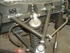
Going by the pic you provided with the -8 7/8"- measurement & the pic from John Ross there appears to be enough of the threaded bush outboard of the weld area to allow you to simply remove enough material to accomodate the locknut. That should allow peace of mind in regard to the 'loose' thread while you investigate the actual settings and means of obtaining them.
Jac Mac

I thought solid, offset upper bushings were a good idea.
Cheers,
Scott
Last edited:
Yeah it is Scott, but I think wear and noise would become a problem with aluminium.
I did a similar thing on my TR7V8 to get rear axle alignment spot on, but used a suitable grade plastic and pinned it with a grub screw going well into the bush.
Cheers
I did a similar thing on my TR7V8 to get rear axle alignment spot on, but used a suitable grade plastic and pinned it with a grub screw going well into the bush.
Cheers
Lynn Larsen
Lynn Larsen
Russ, et al,
Thanks for the input! Russ, your explanation really helped clear the cobwebs for me. My understanding of KPI was exactly as you have describe it: something that I couldn't alter; short of shimming the bearing mounts which I wouldn't even consider doing. But with all of the talk about KPI, I thought that there was some arcane aspect of suspension theory/tuning that had completely escaped me. (Not an uncommon viewpoint, methinks.)
Scott, I can see the value of the eccentrically bored bushes as well! The more I look at the A arms, the more I fear that there is no way to get enough negative camber by moving the mounts foreward to avoid taking the camber positive by the time caster is set using the rod end. So, to use the existing arms while determining the proper geometry for new ones, either machining the far end as Jac Mac says or using eccentric bushes would seem to be the two workable alternatives. The trick to using the bushes would be keeping the eccentrics in phase to avoid binding the hinge action of the A arm.
Thanks!
Lynn
Lynn,
Whatever you do I'm sure it will all work out very well !
Best,
S
Whatever you do I'm sure it will all work out very well !
Best,
S
Lynn Larsen
Lynn Larsen
DRB/GT40 Australia Owners,
Since you guys use 'Vette front uprights, would you care to share front end settings that have worked for you?
Regards,
Lynn
Since you guys use 'Vette front uprights, would you care to share front end settings that have worked for you?
Regards,
Lynn
Lynn Larsen
Lynn Larsen
While it turns out that the "stock" alignment settings for the DRB are very similar to those recommended for the Sabre, it doesn't appear that I can leverage any experience that DRB owners may have developed with their use of 'Vette uprights. See this thread: Lynn's post in the GT40 Australia Owner's Forum
Regards,
Lynn
Regards,
Lynn
Lynn Larsen
Lynn Larsen
Jac Mac,
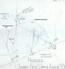
I think you are spot on and this forms the basis for what I am going to choose to believe happened with the design and production of at least some of the Sabre upper A arms. I made some measurements and did some scale sketches of what some different designed A arms would look like. (See sketch below.) They all have ½" rod ends at the chassis pickup points. Two of the arms (A frame arm and asymmetrical hoop arm) set the 3/4" rod end that attaches to the upright in line with the camber adjustment (perpendicular to the direction of travel.) In the A frame version, you can see that the leading leg is very close to perpendicular to the line of travel and it would be even closer when a bush is used as in the Sabre design. Indeed in the Sabre design, the length of DOM tubing is just right: with the design one would have been able to get there (proper alignment settings with lock nut) if the bung had been flush with the end of the DOM tubing as you recognized. I am guessing that the shoulder width of the weld in bung was overlooked until some number of arms had been fabricated such that the cost correcting or recreating the arms was more than Donnelley could bear. (He was already having severe cash flow issues by this time as it turns out.) This is not much of a stretch when one considers that even chasing the threads in the bungs after welding was overlooked also indicating that quality control was not a huge priority at the time.
I think you are spot on and this forms the basis for what I am going to choose to believe happened with the design and production of at least some of the Sabre upper A arms. I made some measurements and did some scale sketches of what some different designed A arms would look like. (See sketch below.) They all have ½" rod ends at the chassis pickup points. Two of the arms (A frame arm and asymmetrical hoop arm) set the 3/4" rod end that attaches to the upright in line with the camber adjustment (perpendicular to the direction of travel.) In the A frame version, you can see that the leading leg is very close to perpendicular to the line of travel and it would be even closer when a bush is used as in the Sabre design. Indeed in the Sabre design, the length of DOM tubing is just right: with the design one would have been able to get there (proper alignment settings with lock nut) if the bung had been flush with the end of the DOM tubing as you recognized. I am guessing that the shoulder width of the weld in bung was overlooked until some number of arms had been fabricated such that the cost correcting or recreating the arms was more than Donnelley could bear. (He was already having severe cash flow issues by this time as it turns out.) This is not much of a stretch when one considers that even chasing the threads in the bungs after welding was overlooked also indicating that quality control was not a huge priority at the time.
Attachments
Ian Anderson
Lifetime Supporter
Lynn
Could you turn your A arms over?
At present your end rod end looks to go rearwards
If you turn it through 180 degrees (the top of the arm becomes the bottom) does that put the wheel in the correct location? It could then be that you can get the nut on without new arms being made (May need to him the unit bacl or forwards to get correct point.
That said I do not know if that would put excess stresses on the units
Ian
Ian that's a good idea !
Although its hard for me to visualize from the pictures if it would give Lynn the room, he doesn't need much for the jam nut. It looks like it might also give him increased positive caster. If it does work, he would kill two birds with one stone.
Any strength issues could be easily solved with a simple gusset.
Its certainly worth a try.
Best,
S
Similar threads
- Replies
- 9
- Views
- 3K