Gas Tank Fabrication
The GTO has been undergoing the homebuilt car sorting out process and has just over 2,000 miles on it now. One of the issues it has had since I moved from a location at 800 feet elevation to a location at 5,100 feet has been a “vapor lock condition” that can occur when ambient temperatures are in the mid 90s F and when climbing a steep grade. Given the EFI, it’s not the traditional vapor lock, it happens when the fuel boils and turns to vapor just prior to the fuel pump thus resulting in no fuel pressure and a stalled engine. After a 30 minute or so break, the fuel cools enough that liquid fuel gets to pump, fuel pump starts working again, and the engine restarts. No real harm, just a grumpy, disgruntled and now overheated driver.
The required fix is to move the fuel pump into the gas tank similar to an OEM factory EFI configuration. Having the fuel pump draw fuel directly from the bottom of the tank virtually eliminates the pre-conditions for this type vapor lock.
Back when I first started building the GTO, I had aspirations of using it as a “track car” and built it with a foam filled bladder type fuel cell using an fuel pump external to the cell. After a 20 year plus build, I decided that it was more prudent to just use the GTO as a street car. My first thought when the vapor lock started happening was to just relocate the fuel pump into the existing fuel cell even though it had gone “out of date” many years ago. Subsequently, I was told by several people that doing this is flirting with more issues as the open celled foam inside tends to break down and start clogging up the fuel system with foam debris.
So I thought, what the heck, I built the car from scratch, why not build a new fuel tank from scratch. The fuel tank is rectangular in shape (34” wide, 17 ½” deep, and 9 ¾” tall) so that should be easy enough to build from aluminum sheet. I’ve had a sheet of .090 aluminum gathering dust for a few years so I already have the raw material on hand.
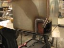
To minimize the welds, I decided to make the bottom and sides from one piece and the top from another. That actually sounds easier than it is unless you have access to the proper folding machines. I found a neighbor with a finger break I thought was larger enough but it wasn’t. Yes, it could bend the .090 sheet but only 2 of the 4 sides could be bent to 90 degrees. The other 2 sides could only be bent 45 degrees as the already bent side hit on the break top bar.
The proper tool for folding a rectangular box this deep is a press brake and I should have sought out one of those. Fortunately, I was able to use the flanging dies on my TM Tech power hammer and some muscle to move the 45 degree folds over to 90 degrees in the .090 thick sheet. The corner seams on the resulting piece were close but had too much gap for good welds. I broke out my TM Tech flow forming tool (i.e. rivet gun with hard plastic hammer head), clamped heavy metal bars inside the box, and “moved” the corner on the short folded sides about 1/16” inward so vertical seams were now tight together.
My plan is to reuse the fill plate and fuel collection box from the fuel cell. The fill plate already has the 2 ½” fitting for tank fill, -8 outlet, -8 return, -8 vent with rollover protection, and fuel level sensor mounted on it. I just need to drill and mount an electrical wire bulkhead fitting into it for fuel pump power.
The plastic fuel collection box has one way valves on 3 sides to let fuel in but not back out. The EFI return line will be plumbed so it drains directly back into the collection box. I’m using a compact Walbro fuel pump which can be mounted with a simple 90 degree bracket inside the collection box. The pump is positioned with a fuel sock directly on the box bottom. This way fuel is gravity fed to the pump impeller until the tank is almost completely empty which should prevent the vapor lock issue.

Onto tank baffling and this is where I could use some input. In my mind, the baffling has two purposes: 1) minimize fuel slosh during acceleration and cornering, and 2) reinforce the fuel tank from the inside out against deformation or bursting. This tank mounts to the chassis with 3 under hung 1 ¼” straps and is free standing in that there are no external bulkheads on the sides or bottom. I believe the .090 thick aluminum is plenty strong for this tank but want to reinforce it well for extra strength/protection. 20 plus gallons of fuel when tossed about with fast acceleration, cornering, and braking can pack a wallop.
My first thought for the baffling was to use 3 across the short direction and 1 across the long direction egg crate style.
The collection box would be held in position between 2 of the baffles with openings in the baffles for 2 of the one way valves. Thus the collection box is fed from 3 different sections of the tank. For assembly and servicing, an access way is needed to the collection box so pump, hoses and wiring can be accessed. For this, the baffle closest to fill plate needs to have a portion that can be easily removed and reinstalled through the fill plate opening.
My first thought was to weld all the baffles to the tank sides and bottom directly. Upon thinking about this some more, I think it might be wise to weld some small angle brackets to the tank sides and bottom then attach the baffles to the brackets with either machine screws or pop rivets. The reason being that there isn’t much room for a TIG torch, filler rod and my big hands inside once the baffles are in place. Also, sightlines to the weld zones will be very restricted and I hate trying to weld without direct line of sight. Anyone have experience with something like this, please speak up with advice.
The other part about the baffles where I could use some input is design. In other words, hole quantity, size, and positioning. I want fuel to readily flow from chamber to chamber during tank filling but resist movement between chambers except for when flowing to the collection box as the tank empties. I’m thinking a couple of larger sized holes up high in each baffle for purposes of tank filling and fuel slosh shouldn’t be a factor when the tank is greater than ¾ full. Then a few smaller holes per baffle, maybe ½” in size, down low so fuel can move via gravity from one chamber to another as tank empties but not a lot of movement due to fuel slosh.
Any input on baffle design would be greatly appreciated. Please include the “why” along with the “how” so we all can learn something here.
In addition, if there’s anything I’ve described as part of this fuel tank project that doesn’t sound right or safe, please don’t hold back. This isn’t my first fuel tank project but I certainly don’t claim much expertise on the subject either.