Air intake pictures

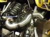
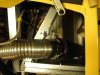
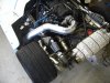
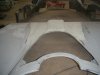
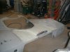
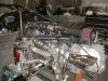
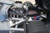
Anybody have any pics of how they're drawing air to the intake manifold from the side scoops. Car is away getting the exhaust done and we mocked it up out of curiousity (I don't have my air tube from the factory yet, and the only pics I've ever seen of it was Cam's using flexible tubing) and neither of us could figure out how the heck that would ever be possible to feed from the side scoop :confused:
 
I think this is Cam's car, but It's all I've got
 

Attachments

  • induction2.jpg
    induction2.jpg
    48.5 KB · Views: 483
  • P8220010.jpg
    P8220010.jpg
    39.7 KB · Views: 442
I've seen his. I'd be curious if he ever did a back-to-back dyno without that corrugated piping - apparently the ridges in it disrupt airflow so it's the same as halfing the diameter of the pipe (i.e., 4'' corrugated piping flows the same as 2'' smooth/round tube)
 
I certainly hope that the flex tubing is a temporary mock up.....looks a little too 'home depot'. Would definitely look better with stainless or aluminum tubing
 
I have to angle of the air cleaner more forward to give a little more room for the inner fender.
 

Attachments

  • Engngine top view.jpg
    Engngine top view.jpg
    187 KB · Views: 550
I went straight back, it involves making a vent in the clip but work great.
 

Attachments

  • AGF00004.JPG
    AGF00004.JPG
    464.3 KB · Views: 429
  • AGF00005.JPG
    AGF00005.JPG
    501 KB · Views: 434
  • AGF00003.JPG
    AGF00003.JPG
    640.5 KB · Views: 502
I have to angle of the air cleaner more forward to give a little more room for the inner fender.

I can't believe that run clears the body and the diagonal cross-bar. that's what I was visualizing, but it sure doesn't looke like it can fit.
 
The Grey car has the engine raised due to the Albins transaxle and the whole tail section modified quite drastically.

Waynes intake will clear just fine as I am sure he has tested it....the left rear roll cage support need to be moved forward from the billet upright attachment point , to locate on the aluminum chassis rail though...
 
If you go to my build it shows the layout of the intake and the modification to the tail to allow the cool air right at the filter, it also helps to get cool air into the motor compartment back where the exhaust runs, it may not be as aerodynamic as the one above but it does work
 
Alex it is too bad I did not know about the exhaust being done. I had a set of headers and exhaust pipes with cads and mufflers and tips for my car made by Heedman/ Hustler headers. They still have the jigs and said he can make the system for $1000 for the headers and I don't know for the exhaust, but I can find out if anyone is interested, this fits a LS7 engine.
 
Bob I called Hedman/ Hustler headers they remember making them for the SL-C but they never kept the jig or any info on them and would have to have the car back to make another set.
Bob could you send me a link to your build I would like to see the air intake.
Cheers,
Grant
 
If you need me to I can take it back to Chris at Heedman/Hustler and let them make a jig. I am on the forum build 002, mine is the second production chassis, let me know if you need specific pictures will be glad to shoot some more.
Good Luck Grant on your build,
Bob D
 
I have to angle of the air cleaner more forward to give a little more room for the inner fender.

Ooooo, I see now, you've relocated the driver roll cage mount!

I've been looking at the picture for days wondering how the heck you were going to clear the brace and it finally just hit me, haha. Yea, I'm slow, sue me :laugh:
 
Are there any concerns with brake dust and other road/track debris? Seems like you would be in for a new filter every thousand miles...
 
Back
Top