
Casey, can you post a pic of the setup? Are you talking about the 1/4 inch black crossmember above the trans? This is a very solid piece on my car, no play at all. It may be particuliar to the Audi trans setup. My inbox is empty now btw. chuck

You are using an out of date browser. It may not display this or other websites correctly.
You should upgrade or use an alternative browser.
You should upgrade or use an alternative browser.
drivetrain/clutch shutter! tranny mounts?
- Thread starter chaparralman
- Start date
No guys. It is NOT the motor mounts and does NOT have to do with the Monocoque.
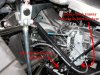
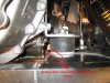
The transaxle mounting platform is made of normal steel. It is part of a sub-frame assembly that bolts to the rear of the stainless monocoque.
It is what the rear bodywork hinges on, what the pneumatic body shocks mount to, and that the tranny mounts to via 2.75 inch diameter cylindical rubber pucks
SEE PICTURE
That labeled thin steel mounting platfor is only 18 gauge steel at best that is merely stiched welded at the edges. The welds are cracking through and the plate is buckeling.
Attachments
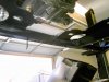
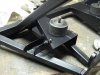
NOW. The mounting pints in the picture is the ONLY support place for the drive train other than the two motor mounts.
Between the softish rubber puck and the flimsy metal, I am getting alot of deflection.
I know it is an inch of deflection because you can see where the tranny has moved downward enough to hit the fram in the rear that is about an inch away.
I have ordered polyurethane from McMaster Carr to replace the rubber with a hard durometer material.
I will strenthen the crappy mounting platform and go with that.
I decided to go this route because, as you can see, the left tranny mount is also a mount for the shifter and this way things stay stockish.
I feel this will work well, but will require more work to strenthen the platform that just solid mounting.
I will let you know how it turns out.
Now I see what you are talking about. The ZF setups do not use that as a mount, although a few guys have added mounts there to support the tail of the transaxle and in those cases they have reinforced the crossmember. I agree this should be a stronger mounting point and even though it should be an easy task, it sucks to have to do it. Look on the CAV forum here and check the threads under putting power to the road or something like that (Childress I think) lots of good info on this and other topics
Hi Casey,
You might find that you have as much movement in the engine mounts as the rear pucks supporting the transmission - that's the case on my CAV at least and I have spent some time studying the situation.
Good luck with the racing and the fix.
You might find that you have as much movement in the engine mounts as the rear pucks supporting the transmission - that's the case on my CAV at least and I have spent some time studying the situation.
Good luck with the racing and the fix.
Last edited:
Hi Casey, you are right about the flimsiness of the trans mount on your car. The newer CAV also use that mounting method for the ZF and I have seen that sheet metal fail.
I cut out the sheet metal and welded in a 1" by 2" rectangular steel mount and that strengthened that area quite a bit.
Dave
I cut out the sheet metal and welded in a 1" by 2" rectangular steel mount and that strengthened that area quite a bit.
Dave
Attachments
AN EXCELLENT FIX!!! to your ZF mount that is.
Does your ZF mount with those two ears above the diff as well?
Why on earth does CAV make this mount so badly when they do other things well.
I took off my sub-frame today and am ready to beef it up.
I noticed that the left side has been broken in the past and rewelded and that is why it is OK now. The right side is VERY broken and the mount is doing little good.
I will post pictures of my sollution.
I am going to reinforce the mount the exists already. Don't make me explain it now, I know it will work well.
The new CAV's do not use the top mount on the ZF, if they did that and used the rear mounts also that would be better.
Dave
Dave
Stumbled on this thread, and I, too, have had this problem. Mine is #29.
Exactly all that you described, and exactly all the same expletives expressed upon discovering the flimsy design. My solution was to weld in small rectangular pieces of steel tubing at all corners of the mount, as well as triangular sheetmetal pieces to support all 90 degree areas. Seems to be working OK now and it did reduce the shudder.
Could you post the part # for the McMaster Carr poly mount?
Cheers! and good luck.
The polyurethane I have ordered from McMater Carr has this part number. 8784K983
It is coming today, so it may not be quite what I want (durometer), but I have good confidence that it will be just right.
It is my intention to cut off two 1.6'' sections that will support the resting weight of the tranny and that will be under compression under acceleration forces. I will also cut off two 1.25' sections that will go on top of the tranny mount to accept engine braking and deceleration forces. I may change the dimensions how I see fit, but those are good starting points.
Think about this if you don't get it. There will be one long bolt that goes through this new assembly.
The stock rubber mounts work to dampen both acceleration and deceleration forces because they stretch on deceleration.
Since I can't bond a small bolt to either side of one Polyurethane puck, I will have one puck on top of the tranny bracket that will compress under deceleration. If you only ran one poly-puck and ran a bolt trough it, then you would have NO damping forces under deceleration forces as you would have the bolt in tension and metal-to-metal contact only.
I will post pics later of the Polyurethane, how I cut it, my new subframe strengthening, etc.
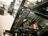
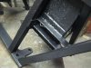
Lameo FedEx didn't "execute" my delivery today, but here are pictures of my strenthening project.
Mind you, I decided to put some undercoating in this area because I know water would get trapped here and you dont see it anyway.
The stock platform remains unaltered.
The two cross beams are incredebly ridgid and are welded to a new platform that fits against and below the old platform. The mounting bolt goes throught the old platform and the new one with JUST enough room to sapre between the cross beams for the nut. The placement of the cross beams is so that the load goes as directly into them as possible so as not to flex flat plate stock like if they were farther apart.
Also, notice the extra length of steel that is welded to the new smaller platform, the cross beams, and the 1 inch square tubing of the sub frame. this is to strenthen the area like crazy so the welds of the cross beams don't break under deceleration forces that want to pull it upward and away from the subframe.
I didn't add much metal to do this project and very little is visible from above. I am very happy with this fix and am confident it will be strong.
Casey
PS. My sponsor deal to go to Europe to race F3 and train for F1 is moving along. Hopefully I will be there testing and training within the month. Wish me luck. Putsch Racing
Attachments
FINISHED and is a BIG difference!!!!!
Hey guys,
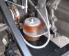
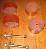
I finished my tranny mount project. The part number I lested from Mcmaster Carr a few posts ago was just right. I am very happy with its characteristics!
The polyurethane was 3"x6" and I was able to cut the right slices off so there was NO excess. Two 1.6" ish long ones and two 1.25" ish long ones. The smaller on top.
Now, I HIGHLY suggest you beef up your mounting platform like me if you use the polyurethane mounts.
The drive train bouncing and shutter is gone and there is NO noise or harshness.
The clutch this engages with a shutter, but that detrimental drivetrain bouncing is gone. I can live with the car now.
This was WELL worth the effort and the car is more solid and will stay together better.
I think all CAV's should have this mod done to them and for everyone to forget the dumb rubber mounts.
Casey
Hey guys,
I finished my tranny mount project. The part number I lested from Mcmaster Carr a few posts ago was just right. I am very happy with its characteristics!
The polyurethane was 3"x6" and I was able to cut the right slices off so there was NO excess. Two 1.6" ish long ones and two 1.25" ish long ones. The smaller on top.
Now, I HIGHLY suggest you beef up your mounting platform like me if you use the polyurethane mounts.
The drive train bouncing and shutter is gone and there is NO noise or harshness.
The clutch this engages with a shutter, but that detrimental drivetrain bouncing is gone. I can live with the car now.
This was WELL worth the effort and the car is more solid and will stay together better.
I think all CAV's should have this mod done to them and for everyone to forget the dumb rubber mounts.
Casey
Attachments
Thanks Coop.
Just be sure to strengthen the mounting platform on your cars subframe.
I can't remember how long the bolts are, they are 3/8 diameter. They ended up being the longest 3/8 grade 8 bolts the hardware store had. Just be sure to get them long enough to go through your pucks and all the steel pars and washers. You don't need grade 8 for this, but they look good. Also, I threw on those aluminum plates on the top because I had them, I should put a washer there, but I am going to replace them with a big steel fender washer.
Casey
Hi Guys
Please have a look at our website. It shows the engine mount upgrade. There is also a gearbox mount upgrade which we will post ASAP.
Thank you for your input, we do take note and we do try and solve such.
Best regards
Jean Fourie
CAV GT | Resurrecting a legend
Please have a look at our website. It shows the engine mount upgrade. There is also a gearbox mount upgrade which we will post ASAP.
Thank you for your input, we do take note and we do try and solve such.
Best regards
Jean Fourie
CAV GT | Resurrecting a legend