Hi Guys,
Looking for some advice which procedure to use to setup initial the suspension. I am not talking about caster, camber or toe yet but the position of each wheel in order to get a symmetrical thrust line (x,y position).
Lets says x-direction is the driving direction.
And y-direction is 90 degrees in the horizontal plane.
All wheels positioned in a perfect square...how to achieve this ?
I measured some points on the GT40 chassis, the rear end beams are not all symmetrical. I noticed this when putting the dimensions in 3D software and copy the right to left side.
Depending on which x-direction chassis rails you take, a new centerline is obtained. There are offset of easily 5 mm so which one to choose ?
What I did so far.
First I used some wood plates and shimmed the garage floor below the wheels to create a level surface for the car.
Secondly I set the ride height roughly 130 mm on all corners.
Third, I used the small long beam above the fuel tank below the door as a reference to start positioning the rear wheel using a small laser.
Noticed some small waveniss along the beam at welds which is normal so I used a straight ruler against this rail to have a straight line.
Set the rear wheels with roughly zero camber, zero toe in and rear uprights 90 degrees (rear lower arm horizontal in x-direction).
The left wheel needed to move 10 mm outwards (y-direction) to be symmetrical to this reference and looking to the body this made sense.
Made the change by turning out the rodends 10 mm both top and lower arm at the left side.
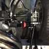
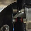
The result is that the long left lower suspension beam (beam connected to the bulkhead of the car pointing in X-direction) is hitting the chassisrail (on the left outer side). The driveshaft length is now 10 mm longer on left side (445 mm left, 435 mm right). Measured driveshaft and is about 440 mm ?
How much play is here maximium allowed ?
Checked the gearbox position towards the lower rear chassis rails and it is perfect centered referenced to that part of the rear chassis.
But it might be off the center by 10 mm choosing another rail ?
Assuming the gearbox is centered.
Which means I have to put the left wheel back 10 mm inwards so somewhere I will keep a misaligned between left and rear wheels towards the current reference.
At the right rear wheel, I am not able to move any further inward (rodends to their minimum) and the low long suspension beam is clearing the chassis rail.
Another boundary is the position of the damper/spring, they can have almost no inclination (Nylon bush type), there is only 5 mm forward position of the wheel upright possible. Need to take this in consideration.
I gonna check if the offset of the rear wheels are identical since I noticed the right wheel needs a 2 mm offset plate to clear the upright while the left doesn't need this offset plate at all. The car came with the offset plate.
Measuring the distance between the front and rear wheels, the right rear wheel needs to move 16 mm forward. But are the front wheels at the same X direction ?
Spoke with my local wheel alignment shop, they said they couldn't check the wheel position but I noticed on their screen there is a module for wheel positioning checking. They never used it before...
What is the easiest way to the measure and setup the positioning of the wheels (x,y position) with DIY tools.
Regards,
Andy
Looking for some advice which procedure to use to setup initial the suspension. I am not talking about caster, camber or toe yet but the position of each wheel in order to get a symmetrical thrust line (x,y position).
Lets says x-direction is the driving direction.
And y-direction is 90 degrees in the horizontal plane.
All wheels positioned in a perfect square...how to achieve this ?
I measured some points on the GT40 chassis, the rear end beams are not all symmetrical. I noticed this when putting the dimensions in 3D software and copy the right to left side.
Depending on which x-direction chassis rails you take, a new centerline is obtained. There are offset of easily 5 mm so which one to choose ?
What I did so far.
First I used some wood plates and shimmed the garage floor below the wheels to create a level surface for the car.
Secondly I set the ride height roughly 130 mm on all corners.
Third, I used the small long beam above the fuel tank below the door as a reference to start positioning the rear wheel using a small laser.
Noticed some small waveniss along the beam at welds which is normal so I used a straight ruler against this rail to have a straight line.
Set the rear wheels with roughly zero camber, zero toe in and rear uprights 90 degrees (rear lower arm horizontal in x-direction).
The left wheel needed to move 10 mm outwards (y-direction) to be symmetrical to this reference and looking to the body this made sense.
Made the change by turning out the rodends 10 mm both top and lower arm at the left side.
The result is that the long left lower suspension beam (beam connected to the bulkhead of the car pointing in X-direction) is hitting the chassisrail (on the left outer side). The driveshaft length is now 10 mm longer on left side (445 mm left, 435 mm right). Measured driveshaft and is about 440 mm ?
How much play is here maximium allowed ?
Checked the gearbox position towards the lower rear chassis rails and it is perfect centered referenced to that part of the rear chassis.
But it might be off the center by 10 mm choosing another rail ?
Assuming the gearbox is centered.
Which means I have to put the left wheel back 10 mm inwards so somewhere I will keep a misaligned between left and rear wheels towards the current reference.
At the right rear wheel, I am not able to move any further inward (rodends to their minimum) and the low long suspension beam is clearing the chassis rail.
Another boundary is the position of the damper/spring, they can have almost no inclination (Nylon bush type), there is only 5 mm forward position of the wheel upright possible. Need to take this in consideration.
I gonna check if the offset of the rear wheels are identical since I noticed the right wheel needs a 2 mm offset plate to clear the upright while the left doesn't need this offset plate at all. The car came with the offset plate.
Measuring the distance between the front and rear wheels, the right rear wheel needs to move 16 mm forward. But are the front wheels at the same X direction ?
Spoke with my local wheel alignment shop, they said they couldn't check the wheel position but I noticed on their screen there is a module for wheel positioning checking. They never used it before...
What is the easiest way to the measure and setup the positioning of the wheels (x,y position) with DIY tools.
Regards,
Andy