

You are using an out of date browser. It may not display this or other websites correctly.
You should upgrade or use an alternative browser.
You should upgrade or use an alternative browser.
Help! Coolant leak
- Thread starter CESLAW
- Start date
Jac Mac
The water pump came with the engine, installed and ready to run. I guess I should not be surprised to learn that the wrong pump was used given the other issues that we have had.
So how do I determine if it is the right or wrong pump? I was not aware that the short pumps came in both configurations, but then I am still at the lower end of the learning curve.
If indeed this is a reverse rotation short pump, there will several other GT builders who got there engines from the same source with the same problem.
I would offer to send a better picture, but we filled the car with coolant, burped the system, and am pleased to report that the valleys on the back of the water pump are dry as the Sahara dessert!
Appreciate your suggestions.
Chuck
Chuck, I can't believe this, but I've got the exact same problem! Roush 351, 1000 miles and just started the same leakage. I closed the hole with JB weld which stopped the leak, but after reading this thread I see the problem. My problem is I'm not sure I can remove my water pump without removing the engine. This is an SPF and the Roush has a large plate for the alternator and A/C that goes over the water pump. I see the rust you got, but I'm still having difficulty understanding how the coolant might get past the rest of the gasket into the timing case? Arggh!
Since it appears Jac and I are sharing a gold star, I figured I better jump in and try to help..
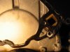
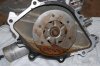
Not sure how much these pictures will help... These are of the 1992 Ford Mustang (counter clockwise rotation) water pump I took apart and cut-up to create a water distribution manifold for my GT40 with Electric water pump. I will get out to the shop after work tonight and take more pictures if needed of the impeller (if I can locate it)..


Given these pictures are of an OEM Ford casting and off of a known CC rotation engine - It would appear that Chuck's casting may be off of a clockwise rotation engine.
The vane style pumps are typically as Jac suggests with the trailing outer edge of the impeller blade - yet it is confusing to look at my picture (impeller) and putting this operational principle to work..
Not sure how much these pictures will help... These are of the 1992 Ford Mustang (counter clockwise rotation) water pump I took apart and cut-up to create a water distribution manifold for my GT40 with Electric water pump. I will get out to the shop after work tonight and take more pictures if needed of the impeller (if I can locate it)..
Given these pictures are of an OEM Ford casting and off of a known CC rotation engine - It would appear that Chuck's casting may be off of a clockwise rotation engine.
The vane style pumps are typically as Jac suggests with the trailing outer edge of the impeller blade - yet it is confusing to look at my picture (impeller) and putting this operational principle to work..
Hey Randy:
A straight on rear shot of the impeller would sure be nice.
Hope it would not be too much trouble.
Thanks
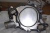
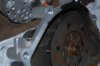
Surprising (well not really) I still had this piece in my shop... Not sure why I saved it - but now I guess I know!
")
Here you go..


Randy and Jac Mac:
Thanks for the pics. Appreciate you going to the trouble. Design has differences, but I would like to agree with Jac Macs analysis: looking at the blade in the 5:00 position seems to suggest it is correct since the blades appear to be opposite.
Sent an inquiry to T and L and got a prompt response:
The water pump should be a standard rotation. The part number is M-8501-E351S and is listed on Ford Racing’s website for V-belt (standard rotation).
Here is a link: http://www.fordracingparts.com/parts/part_details.asp?PartKeyField=5532
Unfortunately the link shows a front view. The documentation with engine did not list a specific part number for the pump, so I can't cross reference it. Ugh.
I plan to go to a parts store and see if I can take a look at a standard rotation and reverse rotation for comparison.
Thanks for alerting me to this issue Jac Mac and thanks for the pics Randy.
Last edited:
Chuck, I can't believe this, but I've got the exact same problem! Roush 351, 1000 miles and just started the same leakage. I closed the hole with JB weld which stopped the leak, but after reading this thread I see the problem. My problem is I'm not sure I can remove my water pump without removing the engine. This is an SPF and the Roush has a large plate for the alternator and A/C that goes over the water pump. I see the rust you got, but I'm still having difficulty understanding how the coolant might get past the rest of the gasket into the timing case? Arggh!
Dave:
Looks like you need to replace the gasket. As Randy pointed out, the accumulation of coolant in that cavity between the backing plate on the water pump and the timing cover will eat up the plate. I was able to clean up the nasty stuff but a leak had been apparent for only a few weeks (but I am sure it had been going on for a long time, just we did not run it long enough to notice).
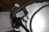
As an aside, in addition to the two holes leading to the two valleys on the back side of the pump, there is a tiny weep hole in the bottom. So even if you plug the two top holes, there should still be some coolant leaking from the bottom weep hole if you have the same gasket issue. Note the attached picture. (Someone with more knowledge than me may want to comment).
Sounds like yours will be a big job. Good luck.
Attachments
Managed to get the water pump out without removing the engine. I didn't have a gasket misalignment like Chuck, but lack of adequate sealer on the gasket allowed coolant to blow thru to the 'vent hole'. I had no rust like Chuck on the back of the steel plate. Someone had mentioned risk of coolant getting to the crankcase, but I can't see this possibility. At any rate 2 questions now:
1. Why are the 'vent holes' necessary ? Seems to me the 1/4" gasket width to the holes invites leakage. What is wrong with closing the holes with JB weld to widen the effective gasket width in that area?
2. What sealant is best to use with these gaskets? Silicones are flexible, but does that allow the gasket to squirm under pressure?
Any advice is appreciated as I don't want a repeat on this.
Attachments
Chuck - No problem... Glad it's all working out...
Dave - I would take the backing plate off the pump and take the whole mess to the local parts house to get the correct gaskets and I'd also pickup a can of Permatex's "Right Stuff". This stuff could be used without gaskets - but as I've said before, you would have a very hard time getting the two parts separated if you ever wanted to disassemble it. A thin coating of Right Stuff on the gasket and clean surfaces (I use lacquer thinner) - assemble and let fully cure (at least 8 hours - overnight is better) before you put coolant into the engine.
The concern about the plate rotting out is no where near as great as the concern for rotting through the pot-metal casting that the timing chain cover is made of. It is **very** thin where it goes over the cam sprocket. If it rotted out, there's where your contamination into the crankcase would come from...
Yes - you could use JB Weld to widen the sealing surface. I'm not sure it would buy you much for the effort. Remember that many of these water pumps / covers go hundreds of thousands of miles with the design as delivered by Ford.
The 'Vent' holes that you refer to are threaded for bolts on the water pumps with a 'scroll' type impellor cavity. The later pumps that you & Chuck have are using are simply a large mixing bowl in this area, dont use these two bolts and rely on the steel intermediate plate to seal thhese two threaded holes of-- if the gasket placement is not spot on and all faces true etc then leakage will occur. The early type pumps are probably more efficient, in fact the early Boss, CJ type motors all had cast impellors with curved vanes/blades for more efficient pumping-- unfortunately the $$ has meant that the elcheapo pressed steel impellor is all you get these days in production pumps.
Dave:
Would you mind posting a pic of the back side of your water pump before you put it back on the engine? I assume you have a serpentine belt / reverse rotation pump. So comparing it to the pic of mine may help determine if I have the right one.
For what it is worth, the gasket was not a precise fit around the bolt holes, so carefully trimmed a tiny bit with a sharp exacto knife to prevent the gasket from catching the bolt threads when tightened down.
Chuck
Jac - Would you have one of these scroll type pumps lying around the shop that you could post a picture of? I think I've worked on most every Ford part out there but the one you mention just does not come to my memory - albeit my memory is no where near what it used to be...
Chuck / Dave - A clear pic of your Timing chain cover without gasket would also show these holes - please post if you have them..
Thanks guys..
Chuck / Dave - A clear pic of your Timing chain cover without gasket would also show these holes - please post if you have them..
Thanks guys..
Chuck,
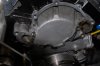
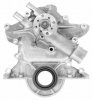
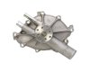
Here are shots of the water pump. The impeller blades look straight. The pump rotates clockwise as you look at the front of the engine with a serpentine belt. There is rust in the pump chamber, probably due to water (not antifreeze) sitting in the engine after dyno run until I installed the engine. Thanks for the tip on gasket trimming. Thanks also to Jac on the hole explanation. Those two extra holes by the water runs are threaded. I'm putting set screws with sealer in them before installation just in case.
Thanks Big Foot-I'll use Right Stuff on the gaskets and liquid teflon seal on the bolt threads that go into the block.
Attachments
Thanks Dave:
Interesting. Looks like we have the same pump, except each spins different directions in our respective applications.
Also note with interest that the blades appear to be perpendicular to the center shaft, not canted like the blades on Randy's.
Jac Mac observed that this pump design is like a "mixing bowl." That seems to be a pretty accurate description based on the blade design.
I am wondering if this pump, as designed, is suitable for rotation in either direction.
Perhaps someone more knowledgeabe could comment.
The Ford Racing site describes it as a "short V-belt water pump." Don't see where they market a short reverse rotation pump, but maybe I overlooked it.
In any event, thanks for posting the pics.
Randy, I unfortunately dont have any better pics of the timing cover.
Randy,Chuck, Dave--- I will dig out front timing covers & pumps & take photos later & post here, There are actually three front timing cover designs for cars trucks plus a Mercruiser design with integral front mounts ( Cast Iron-so dont get excited )
Have some other pics on another matter that HAVE to be added to a file & dealt with first before I can do this so it might not be today.
)Have some other pics on another matter that HAVE to be added to a file & dealt with first before I can do this so it might not be today.
Dave:
A bit of nosing around on the www.fordracingparts.com site revealed two different short water pumps: one for a V belt and one for a serpentine belt. Pics attached. The serpentine belt pump comes with the timing chain cover and the pump itself looks noticeably different in the pics than the pumps you and I are using.
Our pumps look like the "Street Rod Short V Belt" pumps.
FYI.
Attachments
Similar threads
- Replies
- 19
- Views
- 1K
- Replies
- 11
- Views
- 985
- Replies
- 140
- Views
- 6K
- Replies
- 18
- Views
- 1K