I am in the process of rewiring some of my dash switches. The problem I am having is with my electric water pump and dual front fans.
What I have:
Three pole switches with lites on the end of the switch stalk. The poles are power, load, and ground. The pump and the fans are controlled with relays. The load from the switch, goes to the coil of the relays.The thermostat is a two pole unit, which connects the two poles when the temp is met, and it turns on the warning lite.
What I want:
I want the switches to control the appliances. The easy part.
I want the thermostat to turn them on if I forget to turn them on. I also want the warning lite to turn on when this happens(only) as a visual reminder. It will also alert me that the temp of the water is rising and is approaching a danger point.
Here are my thoughts on the matter.
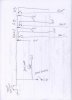
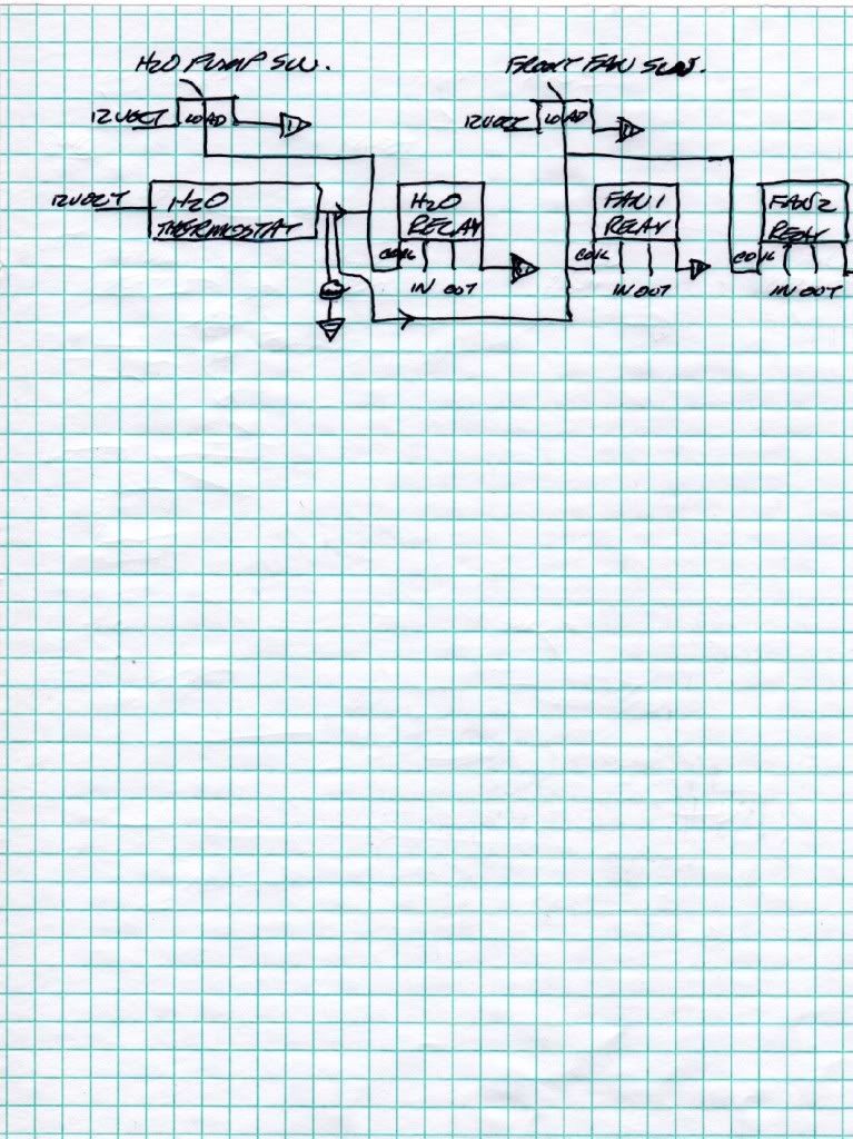
The wiring from the thermostat needs to have a diode or two in line to keep the system from back feeding and turning the lite on when the switch is thrown. Here is my diagram to illustrate the point. The diode is represented by the two arrows. Looking at it after I drew it I can see one doing the job.
My question is, will this work or is there some easier way to achieve it. My next question is if this is the way, which diode is better served here. I got several to try them out. What I am afraid will happen, is the back current from the switch being thrown will cook the diode and lite the lite. I have some 6 amp rectifier diodes. Its values are:
Vrm(wkg)Vr-50VPK
Vrm(non-rep)-100V
Vr'-35V
Io'-6amp@60C
Ir'-25uAdc(u is micro)
Ifm(surge)-400APK
Electrical characteristics
Vf(AV)-.9VPK
Ir(AV)-25uAdc
Some In 4001 rectifier diodes (silicon 1.5A-1000V)
and some IN 5401 rectifier diodes(3A-50PIV)
Any thoughts on this idea??? Will I have to put up with the lite being lit every time I flip the switch??
Bill
What I have:
Three pole switches with lites on the end of the switch stalk. The poles are power, load, and ground. The pump and the fans are controlled with relays. The load from the switch, goes to the coil of the relays.The thermostat is a two pole unit, which connects the two poles when the temp is met, and it turns on the warning lite.
What I want:
I want the switches to control the appliances. The easy part.
I want the thermostat to turn them on if I forget to turn them on. I also want the warning lite to turn on when this happens(only) as a visual reminder. It will also alert me that the temp of the water is rising and is approaching a danger point.
Here are my thoughts on the matter.
The wiring from the thermostat needs to have a diode or two in line to keep the system from back feeding and turning the lite on when the switch is thrown. Here is my diagram to illustrate the point. The diode is represented by the two arrows. Looking at it after I drew it I can see one doing the job.
My question is, will this work or is there some easier way to achieve it. My next question is if this is the way, which diode is better served here. I got several to try them out. What I am afraid will happen, is the back current from the switch being thrown will cook the diode and lite the lite. I have some 6 amp rectifier diodes. Its values are:
Vrm(wkg)Vr-50VPK
Vrm(non-rep)-100V
Vr'-35V
Io'-6amp@60C
Ir'-25uAdc(u is micro)
Ifm(surge)-400APK
Electrical characteristics
Vf(AV)-.9VPK
Ir(AV)-25uAdc
Some In 4001 rectifier diodes (silicon 1.5A-1000V)
and some IN 5401 rectifier diodes(3A-50PIV)
Any thoughts on this idea??? Will I have to put up with the lite being lit every time I flip the switch??
Bill