Lance's GT40 Australia Build

Dave,

You're welcome to come and have a look. Let me know when you're in town. In advance, if possible. Workshop access to be sorted.

I've given up on guessing when it will be hitting the road. My lotto picks have been closer.

I will be putting emergency door actuation inside. I'm actually going to use the standard internal door handles, but mounted on the rear bulkhead. I'll also be running a cable pull to a secret location on the car somewhere for external access in the same scenario. It sounds like a lot of work, but there are several advantages including removing a water ingress point on the doors. My doors have quite a bit of electrics in them. In addition, we're reinforcing the door latch mounts on the bulkhead. The mounting into the tin doesn't fill me with confidence. Hopefully, I'll never need the additional strength.

Regards,

Lance
 
magic job on the pipes, the man must have sand filled them, didnt think the skills had survived this far into the millenium.
now whats with the hoist, elevator. seems very compact. do tell. steve
 
The hoist belongs to the chap working on my car. It's a nice bit of kit. It looks like a pallet trolley, runs off mains power and will lift the car off the ground to over head height, or anywhere in between. No powered travel. Not required with no load and too heavy to move with a load.

Amazingly enough, a company here in Perth was using it, then decided to throw it out when their needs changed! I wish I'd been there that day.

Lance
 
I picked up the oil tank from the fabricator today. It looks great, so had to post a couple of photos. It sits alongside the alloy water header tank and will really look the business.

A lot of work going on with the car just now. Air con lines have been run, seats being finally mounted, so that water lines, centre console, gearshift, seatbelt mounts (harness and lap/sash) can all be installed without interfering with each other. Passenger door all wired, mirrors all wired. Dual SPAL radiator fan unit should be arriving any day now. Remote door latching sorted and being installed. With the oil tank back, the oil lines for the filter, cooler and dry sump can be finished.

In the next few weeks the electrics, air con, cooling, oil and fuel systems should all be finished. The plan is to fire the engine up at that point and see what it sounds like.

Cheers,

Lance
 

Attachments

  • Oil Tank Top.jpg
    Oil Tank Top.jpg
    19.1 KB · Views: 1,039
  • Oil Tank Base.JPG
    Oil Tank Base.JPG
    26.4 KB · Views: 1,024
Your car looks brilliant, Lance. I’m looking at putting an 1UZ into an RF chassis and plan to have the project started in the coming months. Thanks for posting the pics.

The Wizard has certainly done a great job on the exhaust.

Cheers,
Danny
 
Hi Lance

How is your car coming along. I have really enjoyed your build as you seem to be doing a lot of innovative stuff. Plus I love the black wheels with maroon color you are planning to do. How about an update.

Cheers

Jack
 
Thanks for your kind comments Jack. Yes, I love the look too. I do plan on licensing it and then running it for about 12 months before I finally paint it. Maybe just a flash coat to make it all one colour. I’ve seen fresh fiberglass spalling off due to heat (I’ve heard of pieces as large as 5c in diameter) and don’t want to be taking expensive fresh paint with it. I’ll fair up the body after that time and then paint it once the glass has settled down.
The work on the car is taking ages, but it is coming along. There are quite a few areas being worked on at the moment and these are my thoughts behind the way I’m doing things.
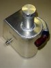
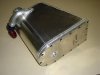
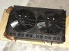
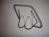
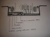
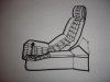
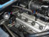
RADIATOR / FANS
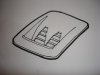
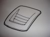
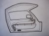
I’ve purchased a SPAL dual fan shroud instead of using the unit I already had. This requires the radiator pipes to be modified (again!), but both fans are the same size, which is an advantage for the ducting I have in mind. I want to ensure all the air goes through the radiator and then out to clear air and not under the front clip. I want to retain the lines of the standard single nostril, rather than a deep vent(s) for this, so I’m proposing to modify the single nostril as per the attached sketches. I haven’t decided on the style of the venting yet. I’m tending towards the louvres.
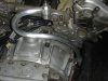
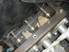
DOOR LATCH
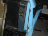
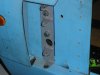
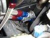
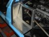
The door catch sticks out quite a bit in the standard configuration and, being fairly big, I figured I’d be gouging my back on it regularly getting into and out of the car. I have to sit on the sill right back up against the bulkhead to swing my feet in. When I decided to go with remote door latching, it became apparent that reversing the catch and latch provided advantages. We’ve welded in sturdy posts to mount the latches to and the actuators live inside, accessible from the engine bay. The flat latch is much more friendly on my back.
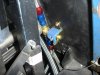
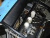
DOOR WIRING
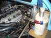
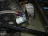
The doors, with electric mirrors, subs and head unit in the passenger door carry quite a bit of wiring. I was concerned about the wiring bundle being crimped through 180 degrees when the doors open and close, so the wiring comes out the end of the door at high level, turns down and then turns through the hinge at a lower level to enter the cabin. This means the wiring only twists through 90 degrees and, being tucked out of the way, is also much better visually.
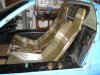
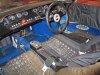
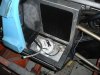
SEATS
I’m using the DRB fiberglass seats. Upholstered in leather, they’ll look great. My seat’s been modified for my size, rotated forward to avoid a Gurney bubble, raised at the front for thigh support and aligned so that it sits as far back in the cockpit as possible. This meant that the amp would no longer fit behind the seat and somewhere else had to be found. We’ve built an enclosure under the driver’s seat and also incorporated the seat rails into it. The Lancia Stratos has a similar arrangement. Out of the car it’s the ugliest thing, but in the installed position, it’s almost all hidden. When upholstered in black, it will be pretty much invisible. The passenger seat has been narrowed to allow the driver’s seat to be offset towards the centre of the cockpit and is fixed to the floor. I’ll be using the GT40 eyelet upholstery and will continue this theme onto the headrest. To reduce the visual bulk of the headrest, I’m planning to use a foldover style of upholstery.
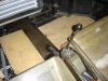
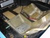
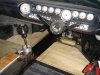
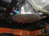
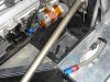
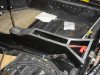
FLOOR
I wanted to keep the floor area open, with no central tunnel. My original intent was to have the floor sitting on a layer of insulation with the services running through it, however, in order to fit my size 12 feet under the steering column (my pedals are mounted further forward in the footwell than usual), this had to be changed and the driver’s side has a lower section in it. Someone with smaller feet than me could keep the floor flat. This arrangement provides maximum insulation from the hot road below. The coolant pipe cover is pressed to include a rebate to support the floor and an angled section on the driver’s side to allow the carpet to run straight over the top. It’s hard to see in the photos, but the pipes also run between the seats and then offset to the left for extra driver foot room.
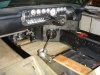
CONSOLE
The console houses the gear stick / Lotus gearshift, switches for the mirrors and door opening, glovebox (with ipod connection inside) and a small glovebox at the rear that also has the heater control and battery key inside.
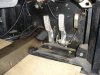
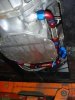
PEDALS
I’ll be installing a footrest to the left of the pedals. It will be the same shape as the throttle pedal. The sloping coolant pipe cover by the clutch allows me to pivot my foot across to the left to use the foot rest. My heels are supported by the cross member running across below the pedals. The pedals are necessarily offset to the left, but by moving the driver’s seat to the left and aiming it at the pedals slightly, the effect is minimised. More room for the handbrake on the right also.
Cheers,
Lance


Attachments

  • Radiator Fans.JPG
    Radiator Fans.JPG
    52.7 KB · Views: 870
  • DSC02386 (Small).JPG
    DSC02386 (Small).JPG
    21.8 KB · Views: 829
  • DSC02387 (Small).JPG
    DSC02387 (Small).JPG
    24.4 KB · Views: 882
  • DSC02388 (Small).JPG
    DSC02388 (Small).JPG
    22.6 KB · Views: 843
  • Door Latch.JPG
    Door Latch.JPG
    34.5 KB · Views: 919
  • Door Wiring.JPG
    Door Wiring.JPG
    26.4 KB · Views: 931
  • Seats.JPG
    Seats.JPG
    57.1 KB · Views: 1,030
  • Floor.JPG
    Floor.JPG
    41.7 KB · Views: 956
  • DSC02390 (Small).JPG
    DSC02390 (Small).JPG
    27.7 KB · Views: 937
  • Seats Console.JPG
    Seats Console.JPG
    51.2 KB · Views: 989
  • DSC02391 (Small).JPG
    DSC02391 (Small).JPG
    30.2 KB · Views: 896
  • Pedals.JPG
    Pedals.JPG
    51.9 KB · Views: 1,081
The interior is coming together now. Final wiring going in. I'll be able to turn on lights, etc soon. A quick check of vent air flows and, if all OK, then I'll be able to get the dash, seats and door inners upholstered.

Lance
 

Attachments

  • Interior 01.JPG
    Interior 01.JPG
    68.5 KB · Views: 890
  • Interior 02.JPG
    Interior 02.JPG
    66.4 KB · Views: 957

Peter Delaney

GT40s Supporter
Hi Lance,

You have done a brilliant & innovative job. It looks like you have got all the hard stuff sorted out now, so the rest should be easier & faster. Not too long now !

I only have 2 complaints about your build :

1. I wish you had started it 4 years earlier - then I could have "borrowed" some of your experience & great ideas !

2. Perth is too far away from here !

PS :

I totally agree with your approach of leaving the final bodywork & paint till much later - I wish that I had done that ! We prepped my car to perfection (final 400-grit block-back over a guide coat), but within a year we had 2 problems :

- some minor sink-holes appeared on the flat part of the front clip behind the nostril panel & the flat areas of the rear clip under the window.

- minor rippling showed up on the flat sections of both clips.

There were no problems at all on any areas which were compound curves (guards, doors, etc), only the flat areas. When I do the inevitable re-finish on the body, I will be looking at re-inforcing these flat areas (maybe using a foam sandwich approach like the RF cars).

Kind Regards,

Peter D.
 
Looking good Lance. I was wondering when you were going to update again. Whar are the round switches near the gear stick for (Air con, heating etc?)

JW
 
Lance,
You went with the Tilton setup as I did. Did you move the center console(or what is left of it) over? You kept the pedals at their standard width I am sure for you large feet(mine are 10s). I removed 3/4" from between them. I have reduced the console height from the shifter forward as it will allow the room needed for the gas pedal which will be angled similar to yours. To do that I bent the cooling pipes to lay flat along the floorboard.I would like to see the details of your gas pedal. My plans(in my head at present) are along the same as yours. Would like to see the layout a little better. If you have some pics of the construction phase I would like to see them as well.

Bill
 
Last edited:
Peter,

Thanks for your comments. Yes, it is moving along, although still a lot of things to sort out. I can see the light at the end of the tunnel. I think.

I’m sorry to hear about your having to do the body preparation again. It must be annoying. Your comment about the flat areas is a particularly good one to have though. When my seat shells were modified, they were quite floppy, but, once the fit was correct a layer of Coremat was glassed in. The Coremat was quite thin, but the difference was amazing. The seat shells became very stiff. As a result of your experience, I’m going to reinforce the flat areas of the body with a layer of Coremat. Thanks for the tip.

Jack,

There will be three switches in the console with round knobs that match the dashboard knobs. The front one is actually a joystick (ex Porsche 911) that adjusts the side mirrors. The middle one selects which mirror to adjust. The rear switch selects and open the car doors. I located these switches on the console because they ‘fall to hand’ quite well and the dashboard switch allocations had all been made.

I note that my dashboard has caused some consternation amongst the Locost UK chaps whose website indicates that many of them think it’s OTT. It’s a modern, street version of GT103’s dash, which is quite busy (see image). It’s obviously not to everyone’s taste, but is exactly what I was after.

Bill,

My console has been moved over to the left, but stops at the front of the seats anyway. The coolant pipes continue forward under the floor, so that there is plenty of room for my feet. I bought the Tilton clutch and brake pedals only and we made a pedal box to suit. The pedals are set out to match those on my old Peugeot 205GTI, which worked really well, even with my size feet. Some adjustment is possible. I don’t have a photo of the gas pedal, but will take one to post. The pedal operates a lever on the left of the coolant pipes with a bare cable (less drag) which will run rearwards to a 1:2 lever arrangement. The cable will then run through the bulkhead, at which point it will have an outer as well, and up to the throttle bodies.

On completely another issue, and I must be mad to go public on this before I‘ve had a chance to test it, but here goes:

I’m spending a lot of time trying to get the ventilation in my car to work correctly. GT40’s are notoriously hot, but I want to use mine a lot, so I’m trying to keep the interior as cool as possible. Fresh air vents are installed to keep the cabin air turning over and to avoid stuffiness. The trouble is though: where to vent the air? The usual locations are a vent on the roof or in the rear bulkhead, but I don’t want to do either. Instead, I’ve come up with the proposal to vent the cabin air through the wing mirrors(!). Please refer to attached sketch. I assume that there should be a slight vacuum behind each mirror (I’m going to check how much with a manometer) and this should bleed off the cabin air to allow for cabin fresh air top up. It’s a bit of an ‘out there’ idea, but hopefully will work well enough. Simple and light. Keep your fingers crossed for me.

All the best,

Lance
 

Attachments

  • GT103_25 (Small).jpg
    GT103_25 (Small).jpg
    61 KB · Views: 939
  • Door Vent.JPG
    Door Vent.JPG
    40.4 KB · Views: 835
Lance, your build is innovative and interesting, and it is enjoyable to follow a builder rethinking the approaches to areas without merely replicating the original. For a road car that is intended to be used frequently, you are doing all the right things to keep it drivable and user-friendly, which is a different approach to either the super accurate replica, or the competitive racing sports car.

I have a thing about air conditioning, and always like to get car air systems working well. Most GT40 replicas with air conditioning seem to merely recirculate cold air. The fresh outside air has to be introduced separately. This may be via an aviation type air scoop in the side window (I forget the proper name; old age). It has been interesting to read of some builders on the forum taking outside air from a front clip intake and ducting it to a plenum on the air conditioning intake, via a manual volume damper. If you run part or all outside air, through the air conditioning supply fan, you get a good positive pressure from the ram effect (moving at speed) plus fan, which easily expels old air from the cabin.

Looking at your proposed relief arrangement, while your concept is a good one, I think you should definitely check the pressure at the mirror housing with a manometer first as you suggest. Then I suspect you will need larger ducting or the friction and small cross section area of the ducting will reduce air flow to a level not worth bothering about. With the bulkhead right behind the seats, if you don't want a roof vent there aren't many options. Could you vent through a slot in the bottom or trailing edge of the door, outside the location of the rubber sealing strip? Any noise issues could be addressed with acoustic insulation in the door around the slot to provide attenuation. Just a thought.

Dalton
 
Work on my car is progressing fairly well. Most of the systems are complete now. Some odds and ends still to do, but big chunks of work done. I’m extremely happy with the results. It still looks a bit of a mess, but it’s getting there.
Oil System
The dry sump system uses the stock oil supply pump. The supply from the remote tank is through the sump pan so that, if the engine blows up, all the components can be swapped to a new block with no modifications required. Two pick-ups return the oil to the remote oil tank via the scavenge pump. A sump vacuum sensor will tell me if the scavenge pump stops drawing (say the drive belt breaks). The stock pressure sensor is used to confirm supply to the engine. A drain hose runs from the tank underside down to a screw cap mounted on the lower chassis.
An oilstat controls the flow through the oil cooler and gives the oil a chance to warm up on cold days. The oil cooler is mounted in a shroud and sealed against the clip so that all the air coming through the vent will go through the cooler. It’s set back so that any stones will hit the back panel and not the cooler. We couldn’t quite fold the shroud out of one piece, but it will look good when welded. The oil cooler shroud will look the same from both sides.
We were having trouble running the oil lines and fitting all the kit up against the bulkhead. The solution was to mount the filter back on the gearbox. This freed things up and makes it easier to drain / remove. The idea came from a forum member’s car. I don’t have his name, but thank you, sir.
Fuel System
Two separate fuel circuits (one for each fuel tank) each supply the fuel rails. Selecting a tank turns that pump on and shuts off a solenoid on the return line to the other tank. Each circuit has a Volvo fuel filter mounted on the bulkhead. Good filters, cheap and easy to source.
I was looking at using resistors to dampen the fuel gauges, but the level sensors come with inbuilt dampening, so that wasn’t necessary. The tanks have a small sump and internal baffling to resist surging. We’ve calculated that it would take 20 minutes of a constant downhill run with an almost empty tank to lose fuel supply.
Heater
Rather than draw hot air from the radiator or tee hot water off the radiator pipes, heater water comes from the engine itself to get the fastest hot water possible. More of a pain to build, but much more efficient. A small radiator has been put in front of the dash mounted Sanden AC unit. The cross beam air duct has had the holes opened up. The standard arrangement looks like it chokes the airway for the fan too much.
Electrics
The brake switches have been mounted on the master cylinder push rods. A collar on the rods actuates the brake and clutch (cutout for the cruise control) switches. They all live in a box which tidies things up and keeps them clean. A bulkhead plug on the box will be used to connect them into the wiring harness.
We were concerned about water from the front clip getting down into the fuses and relays. The answer was to sink them into the cockpit and put a cover plate over them. I‘m using perspex for this so that you can see them and the Tilton pedals. If I don’t like the look, I’ll change it to an alloy cover plate.
We’re required to have brake failure warning lights here. The master cylinder reservoirs didn’t have them, so they had to be added. E type Jaguar switches were fitted to the caps and do the job. Early Jags use switches, late Jags have sensors. Remember to get the correct ones.
I’m using twin batteries to leave the usual location free for other things. Smaller batteries fit out of the way a bit better and you can have one go south on you and still push start the car. We made up fibreglass battery boxes to suit the location available.
Console
The alloy trim to the console has been made. The alloy gearshift surround and gate is being machined now. The gearshift cables will be covered by the floor of the rear compartment. Kill switch hidden in there along with the control for the heater, which can be seen behind the bulkhead. An extension handle to control this is being made up now. Switches for doors and mirrors are being mounted on the sloping section now.
The bulkhead panel is being made up now. I’m going to try a clear perspex bubble to cover the blower drive pulley (noise permitting). It will let you see the engine spin up by your shoulder and should scare a few passengers.
 

Attachments

  • Dry Sump 01.JPG
    Dry Sump 01.JPG
    40.2 KB · Views: 563
  • Dry Sump 02.jpg
    Dry Sump 02.jpg
    26.2 KB · Views: 601
  • Oilstat.JPG
    Oilstat.JPG
    47.7 KB · Views: 495
  • Oil Cooler Shroud.JPG
    Oil Cooler Shroud.JPG
    42.8 KB · Views: 617
  • Oil Tank.JPG
    Oil Tank.JPG
    59.6 KB · Views: 6,113
  • Oil Filter.JPG
    Oil Filter.JPG
    39.9 KB · Views: 474
  • Fuel System 01.JPG
    Fuel System 01.JPG
    60.9 KB · Views: 534
  • Fuel System 02.JPG
    Fuel System 02.JPG
    48.1 KB · Views: 511
  • Fuel Solenoid.JPG
    Fuel Solenoid.JPG
    48.4 KB · Views: 458
  • Heater Pipe.JPG
    Heater Pipe.JPG
    43 KB · Views: 574
  • Brake Switches.JPG
    Brake Switches.JPG
    37.7 KB · Views: 512
  • Bulkhead.JPG
    Bulkhead.JPG
    52.8 KB · Views: 504
  • Battery Boxes and Oil Tank Drain.JPG
    Battery Boxes and Oil Tank Drain.JPG
    55.3 KB · Views: 542
  • Console 01.JPG
    Console 01.JPG
    54.5 KB · Views: 617
Hi Lance

Great to see some updates at last on your build. It is looking the goods and should be a ripper on the road.

Cheers

Jack
 
Hi Lance,

The car is looking really good, and you're making excellent progress. I wish I was ploughing on too, but things have stalled a little. I'm just waiting for that next burst of enthusiasm!

I'd like to see it one day, the only DRB that I've seen over here is Julian's, and that was just before it was licenced. I'm always keen to see how others have tackled similar issues as mine, and maybe reply in kind.

Good luck with it!
 

JohnC

Missing a few cylinders
Lifetime Supporter
Lance, just curious, why did you decide to keep the dissies and the OEM ignition system? I'd have thought you'd be using a crank triggered ignition with some COP's? Did you need to keep them because of your EMS?

John
 
Thanks for your kind words, chaps. Although there is still loads to do, for the first time, I actually feel like the car's approaching completion.

The motor is to go through licensing ADR'd with distributors. I'm planning to change them out afterwards. In addition, I'm trying not to do anything that isn't absolutely required to get it over the pits.

Regards,

Lance
 
Back
Top