Lance's GT40 Australia Build

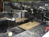
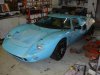
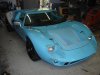
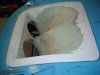
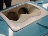
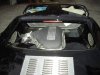
Thought I’d post a couple more images of the project. The interior is coming along nicely now. The centre console, ‘flat’ water pipes and two level floor concept works well. Mounting points for the 6 point racing harnesses have been selected and running the throttle cable is the last item to be sorted before stripping everything off, a quick period of miscellaneous welding and then blast and paint the chassis for (hopefully) final assembly. Still a lot of small things to do, though.

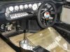
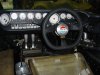
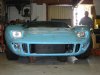
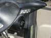
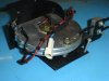
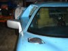
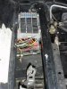
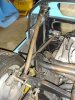
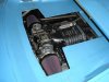
This is the first time that the dash, steering column and wheel has been in the car at the same time. I’m pleased with the way it’s coming together. It doesn’t look much yet, but should look good when finished. My interior theme is for black leather and carpet contrasted with alloy trims. The console switches are in and the gearshift gate is being fabricated now. The gearshift collar in the photos is still to be cut down to the correct height. You can’t see it in these shots, but the alloy adaptor between the steering wheel and column has come up well.

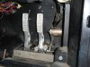
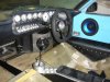
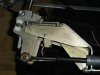
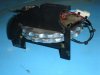
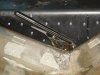
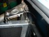
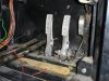
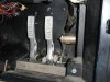
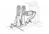
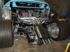
The roller throttle pedal mock-up is in place. The throttle pedal will be reversed so that the lever is on the right and the roller on the left. The roller will be made to the correct length for heel/toeing. The block below the pedals is to support my heels correctly and will be replaced with something a bit more elegant. Getting room for my size 13s has been quite a problem.

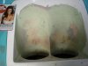
I’ll be getting the seats, dash, etc upholstered and sorting out some other machining, etc, while the chassis is being painted.
 

Attachments

  • DSC03373 (Small).JPG
    DSC03373 (Small).JPG
    59.3 KB · Views: 741
  • DSC03382 (Small).JPG
    DSC03382 (Small).JPG
    51.2 KB · Views: 795
  • DSC03384 (Small).JPG
    DSC03384 (Small).JPG
    42.8 KB · Views: 722
  • DSC03385 (Small).JPG
    DSC03385 (Small).JPG
    45.1 KB · Views: 755

Peter Delaney

GT40s Supporter
Lance, you are powering along - the reduced tunnel / dual floor idea is brilliant !

At the risk of "teaching Grandma to suck eggs" - a couple of suggestions :

- Don't forget to put inspection/access panels in those side panels under the dash ends.

- Have a think about making up a thick plate with 3 x captive nuts for the inside of the door hinge mounting & open up the holes thru the body a bit - any door alignment changes will then be child's play via the bolts on the outside of the hinges.

I did neither, & regret it to this day !!

Kind Regards,

Peter D.
 
Peter,

Thanks for the suggestions. The interior panels are designed to be removed easily, if required, so OK there. Aligning the doors would be awkward at the best of times, doubly so in my case. The passenger door has the sound system head unit mounted in there. I’ll definitely be using your idea. Thanks again.

I’ve attached a few more images. The micro switch on the gear shift for reverse has worked out neatly. The front indicators are neat and, as far as I’m aware, legal, but being small, it’ll be interesting to see if they raise any eyebrows during licensing.

Regards,

Lance
 

Attachments

  • DSC03391 (Small).JPG
    DSC03391 (Small).JPG
    45.9 KB · Views: 622
  • DSC03388 (Small).JPG
    DSC03388 (Small).JPG
    37.6 KB · Views: 586
  • DSC03390 (Small).JPG
    DSC03390 (Small).JPG
    41.6 KB · Views: 712
  • DSC03393 (Small).JPG
    DSC03393 (Small).JPG
    49.6 KB · Views: 709
  • DSC03287 (Small).JPG
    DSC03287 (Small).JPG
    34.7 KB · Views: 747
Lance, looking good.

Can I ask what you have used for front indicators? They look like the little hella side indicators with square base, round top.

If they are ADR 6/00 compliant they are ok, if they are side indicators or outline markers they are technically not compliant.
 

Dimi Terleckyj

Lifetime Supporter
Hi Lance

From my experience with the rego process and the Aust Design Rules your front indicators wont pass the luminance or the field of view requirements.

They have to have a certain level of brightness and from where they are mounted will not be seen from the required viewing angles from the front and sides.

I have much larger approved front indicators and still had to move them forward to allow the field of view required to get them passed.

The photos show what I had to do to get them passed.

Dimi
 

Attachments

  • Picture 037.jpg
    Picture 037.jpg
    88.7 KB · Views: 932
  • PICT0266.jpg
    PICT0266.jpg
    44.5 KB · Views: 808
Last edited:
Yes, it’s going to be interesting isn’t it?

With my car I wanted the look of the round driving lights, but also wanted to mount the indicators there as well. Obviously, this meant that, with little room left over, the indicators had to be small. The only item that fitted was the Hella side light (well spotted) and it’s just what I was after. I haven’t been able to read the full ADR, but the main requirements for front indicators seems to be that they are 21W (for level of brightness) and achieve certain vision angles. The Hella units don’t allow 21W globes so we built our own housings to suit the Hella lens, the only part of the unit we used. I haven’t checked the angles accurately yet, but it looks to be close. There seems to be differences in how each state, etc interprets or implements the requirements. Anyway, we’ll see how it goes. If any of this is a problem with the authorities, I’ll be mounting some auxiliary indicators.

Regards,

Lance
 
Nostrils

These photos show the plug for the nostrils for my car. It’s in the last stages of being faired up and the mould will be cast from it soon. I’m incredibly pleased with the look (not surprising when you can see where the inspiration comes from) and they should be really efficient in dumping the hot air to atmosphere.

Heater Controls

We bought an heater control from a TVR on Ebay. I don’t like most of the heater controls I’ve seen. They’ve all been too modern or too clunky. On the other hand, the alloy TVR controls look great. To me anyway. Finding a suitable location for them, in the busy GT cockpit, was a bit hard, but an acceptable position was located, in the end. In the installed location, they fall to hand easily. You rest your fingers on the dash and move the wheels with your thumb. One wheel diverts fresh cool air into the cockpit; the other diverts heated air into the cockpit. Note the built in LEDs that shows the position of the control wheels. The dash will be covered in leather, which will trim the opening correctly.

Porsche Wing Mirrors

Just in case anybody is thinking of using my wing mirror solution of using Porsche wing mirrors, be warned that, in addition to setting the angles of the mirrors differently for left and right hand drive, those cunning Germans have also located the mirrors differently on each side of the car. Something I’ve never noticed before. The effect is that you need a mixture of right and left hand drive mirror parts, and a machined adaptor, to set them up correctly. Not too huge a task, but not all bolt on either.
 

Attachments

  • DSC03473 (Medium).jpg
    DSC03473 (Medium).jpg
    26.7 KB · Views: 578
  • DSC03465 (Medium).jpg
    DSC03465 (Medium).jpg
    26.2 KB · Views: 504
  • DSC03466 (Medium).jpg
    DSC03466 (Medium).jpg
    28.6 KB · Views: 582
  • DSC03461 (Medium).jpg
    DSC03461 (Medium).jpg
    40.3 KB · Views: 614
  • DSC03415 (Medium).jpg
    DSC03415 (Medium).jpg
    27.8 KB · Views: 588
  • DSC03416 (Medium).jpg
    DSC03416 (Medium).jpg
    29.6 KB · Views: 578
I haven’t posted an update in a while, so here’s a few shots of a few of the things that have been going on.

The roll bar braces have been developed and now include the clip latches. The braces and latches can be removed for easier access when working on the engine, if necessary. The top rear coilover support has been extended to the rollbar brace mount to tie everything together for strength.

Instead of having the fuses and relays under the front clip "in the weather", they’ve been lowered down into the volume over the pedals. In this way they’re in the interior of the car, a more benign environment. Access is still from the front clip area by removing a panel. The panel is perspex, so that the fuses and pedals are on display.

Clip location is by a pin and conical bucket arrangement.

The Porsche mirrors have been set up. When sitting in the car, you have a good field of view. The outside of the mirrors are about ½" wider than the rear guards.

I’m using a Trigger handbrake. Stainless steel, sidemount; a nice unit. The original intent was to mount it on the inside of the sill, but, as room is tight and it had to be located at the narrowest part of the seat to have adequate finger room to operate it, I’m mounting it on the seat base in the ideal location. I’ll always have the seat fully back, but when the seat is moved forward by other drivers, the handbrake lever will move with it and always be accessible.

Regards,

Lance
 

Attachments

  • DSC03836 (Medium).jpg
    DSC03836 (Medium).jpg
    46 KB · Views: 530
  • DSC03840 (Medium).jpg
    DSC03840 (Medium).jpg
    33.9 KB · Views: 498
  • DSC03843 (Medium).jpg
    DSC03843 (Medium).jpg
    26.3 KB · Views: 576
  • DSC03845a (Medium).jpg
    DSC03845a (Medium).jpg
    19.1 KB · Views: 517
  • DSC03848a (Medium).jpg
    DSC03848a (Medium).jpg
    32.2 KB · Views: 557
  • DSC03852 (Medium).jpg
    DSC03852 (Medium).jpg
    42.7 KB · Views: 578
  • DSC03854 (Medium).jpg
    DSC03854 (Medium).jpg
    37.9 KB · Views: 550
  • DSC03857a (Medium).jpg
    DSC03857a (Medium).jpg
    35.3 KB · Views: 590
I’m proposing to open up the area under the rear window on my car. In standard configuration the opening is a bit too small for the throttle body controls, but I want to put more of the engine on display anyway. I think the blown engine looks great and it’s a bit of a shame to hide too much of it. At one stage I was looking at a "T" shaped opening, but it will probably end up being rectangular. I need to surround the filters, etc with a heat shield, for obvious reasons, and I’m planning to have the clip close against this so that (hopefully) only cool air goes into the engine.

My question is: has anyone else done this to a GT40? Are there any photos available of GT40s modified in this way?

Any assistance greatly appreciated,

Lance
 

Attachments

  • DSC03858 (Medium).jpg
    DSC03858 (Medium).jpg
    29 KB · Views: 526
  • DSC03864 (Medium).jpg
    DSC03864 (Medium).jpg
    62.8 KB · Views: 680
  • DSC03866 (Medium).jpg
    DSC03866 (Medium).jpg
    60.9 KB · Views: 667

Dimi Terleckyj

Lifetime Supporter
Hi Lance

I did pretty much what you are asking with my 40 as the 5.4 Boss motor is so big I had no choice but to open the inside of the clip to allow the body to fit around the motor.

You can see how much I had to cut in the enclosed photo.

Looking at your photo be very careful to re route any hoses/cables as far away from the exhaust headers as possible.
I notice what looks like a rubber hose just under the exhaust header.
The amount of heat that builds up under the clip especially when you are driving in heavy traffic with no airflow is immense and will cause any exposed bits to burn or sustain heat damage.

Driving in heavy traffic on really hot days can cause major problems.

Dimi
 

Attachments

  • PICT0082.JPG
    PICT0082.JPG
    64 KB · Views: 738
Gas Pedal / Accelerator Pedal

Bob,

As requested.

I bought the Tilton pedals only and made a pedal box that fitted into the floor pan. I wasn’t sure if the Tilton pedal box would fit properly. The original intent was to mount a typical gas pedal off the box and run the shaft under the water pipes to a bearing support on the passenger side of the pipes. The cable (no outer) would run back under the raised floor section. Refer image.

Then I looked at a roller gas pedal arrangement. The mock-up was better, but still left room for improvement. Image attached. I was also concerned about the gas pedal lever getting in the way of my foot.

The current proposal is shown in the attached sketch. The intent is to support the gas pedal shaft on a rose / heim joint style fitting mounted to the side frame member. This shaft then runs through, and is supported by, the pedal box. There is a spline at this point that allows the shaft to be adjusted without removing the pedal box. This end of the shaft is still supported by a bearing support off the floor. I’m using a quadrant section to pull on the cable. The gas pedal lever is mounted to the right and cranked over into the volume between two chassis uprights. This keeps it out of the way and allows the use of two stops mounted to the verticals to be used to adjust the pedal travel. It sits closer to the side than I’ve shown in the sketch, so that you can see the shaft mounting arrangement.

I quite like the concept and think it will work well. The only trouble is that, while suiting a right hand drive car, it may not transfer into left hand drive. Anyway, there you have it. I hope this helps.

Regards,

Lance
 

Attachments

  • Pedal Proposal Original.jpg
    Pedal Proposal Original.jpg
    50 KB · Views: 519
  • Pedal Proposal Roller.jpg
    Pedal Proposal Roller.jpg
    43.5 KB · Views: 579
  • Pedal Proposal (Large).jpg
    Pedal Proposal (Large).jpg
    32.5 KB · Views: 577
Here's what I ended up doing with the opening above the engine. The T shape works OK and looks good. To me anyway. It'll make more sense when the shrouding around the filters, etc is in place, but I won't do that until after licensing. I'm thinking carbon fibre will look good.

Lance
 

Attachments

  • DSC04168 (Large).jpg
    DSC04168 (Large).jpg
    37.5 KB · Views: 608
Hi Lance

I like the T cut out. It looks great. Yet another very nice personalized touch to your car to go along with many others. It is going to be great when you finish.

Regards

JAck
 
Hello Gus,

Thanks for your query. Sorry about the tardiness of my response. I was travelling when it was posted and I hadn't noticed that my build log had been added to.

The car has been going a bit slowly until recently. At the moment, it's being stripped back to the bare chassis for painting and then final re-assembly. The cats/mufflers and clutch slave cylinder are being sorted as it's coming apart. These are the only significant items. There is also a punchlist of small stuff too.

The goal now is to get it to licensing as soon as possible.

Regards,

Lance
 
After a few unfortunate delays and rework, it's getting closer now.

Lance
 

Attachments

  • DSCF1002 (Large).JPG
    DSCF1002 (Large).JPG
    124.4 KB · Views: 1,038
Back
Top