

You are using an out of date browser. It may not display this or other websites correctly.
You should upgrade or use an alternative browser.
You should upgrade or use an alternative browser.
Making a gearbox adapator, is this okay
- Thread starter mark chandler
- Start date
Here's how I configured my flywheel/clutch for an 01E. A flex plate with a Quartermaster button flywheel for an 8 1/4" (209mm) clutch (good for 400+HP). I did have to fabricate a 28mm spacer on the clutch face portion to move everything back to fit the gearbox bellhousing and input shaft spline. I had everything balanced (it required less than 15 grams correction). Hope this gives you some ideas to help with your adaption.
Andy
Andy
Attachments
Hi Yes I agree an spacer does sound very nasty but it will not long bolts extending through spacer, ring gear plate et al to the crank.
Rover in there wisdom when fitting the ZH auto boxes into classic rangerovers used two plates, one for torque convertor, one for the ring gear, with a spacer in between (its quite large by the way), this lump of metal is drilled and tapped for the torque plate onto which the convertor lives.
I do however share your concerns, a flywheel exiting at speed from the bell housing is not going to be pretty.
I,m going to amass my pile of bits and pieces in the next few days, once all on the ground I,ll review the options, to be honest as a 240mm clutch can take the power then its half the weight of the Rv8 10.5" clutch and cover so that is definately a good thing.
Thanks again for your advise.
Regards Mark
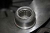
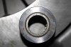
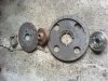
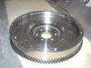
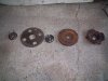
This is what you get from a ZF auto Range rover,
From left to right,
Crank adapator
Starter ring gear
Spacer
Torque flex plate
Tin top plate
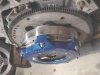
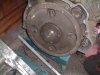
I have cut down a manual bell housing for an adaptor, you can see it clamped to front of the Audi bell housing. Its not a bad fit (it connects well in a number of places) so I will weld on tomorrow, fill the holes and then just need to machine down the spacer above to fit the Audi flywheel and discard the rest, job done.
NB, the spacer is very solidly made and locates into the crank so its not going anywhere.
From left to right,
Crank adapator
Starter ring gear
Spacer
Torque flex plate
Tin top plate
I have cut down a manual bell housing for an adaptor, you can see it clamped to front of the Audi bell housing. Its not a bad fit (it connects well in a number of places) so I will weld on tomorrow, fill the holes and then just need to machine down the spacer above to fit the Audi flywheel and discard the rest, job done.
NB, the spacer is very solidly made and locates into the crank so its not going anywhere.
Attachments
Last edited:
Hi all,
I have now got my pile of parts together as follows:
Rover v8 engine
Rover flywheel
Rover clutch cover & 10.5" driven plate
Various rover gearboxes to supply ali bolt pattern and 1st motion shaft.
Audi transaxle
Audi clutch cover & 240mm driven plate
The rover clutch is larger but looks like it will fit in the transaxle, the flywheel will however not so what I am proposing is:
Chop front off RV8 bellhousing to accomadate Flywheel and machine flat.
1/4 steel plate bolted across this and drilled to suit Audi bolt pattern
Recover splined centre from Audi clutch, machine RV8 1st motion shaft and make a first motion shaft extension to use RV8 clutch.
Extend standard audi clutch actuator to suit.
Can anyone see any issues with extending the 1st motion shaft by 2", I will sleeve so its and interference fit on the existing item and stays true.
Cheers Mark
Just a suggestion,
I guess that the clutch release bearing is concentric.
In this case his axial positioning shall take care of the clutch wear which is normally the same stroke that you use for the complete clutch opening.
Meaning:
Check the total stroke of the clutch release bearing.
Bolt the clutch on the flywheel as it shall be and go under a press.
Push on the fingers in order to open the clutch until the disk is free for his natural independence while shifting and add 1mm.
Example of positioning calculation:
Total clutch relaease bearing stroke: Ex =16 mm
Stroke requested for clutch opening: Ex = 8 mm + 1
Stroke for wear adjustment left is 7 mm.
This is the way to find the exact position of the adaptor lenght.
Ciao
Wanni
Seeing the above has got me thinking again now, great looking stuff by the way.
On Zf auto boxes on RV8's you get a spacer, torque plate with ring gear (seperate plates oddly enough) so I could maybe machine down the Audi flywheel and attach in place of the torque convertor, knock up an adapator ring and should be nearly there.
The challenge is as I see it get the face of the flywheel 3cm inside the standard Audi bell housing, small clutch though !
or
Extend the first motion shaft 7 cm out and make an adaptor that will accomadate the Rv8 flywheel and cover (had another look, cover will not fit in that little hole either).
or
Get angry with the transmission and cut the front off (make a note not to destroy the Transmission or will have to repeat things) and get welding on my Rv8 housing.
The attraction of the RV8 clutch is size + lots of suppliers so cheap as chips. Can you get a 10.5" plate with Audi centre , maybe chop out the centre of the audi driven plate and weld into the Rv8 driven plate, voila !
Will a 240mm clutch take 250 - 300 BHP ? YES, IF HAVE PROBLEMS SEND THE ORIGINAL DISK TO A CLUTCH MANUFACTURER AND CHANGE THE ORGANIC FACING WITH ONE CALLES "RASBESTOS". IT IS USED BY ALL THE GUYS CONVERTING CARS IN BULLET PROUFE. THIS MATERIAL IS BLACK AND IT HAS A FRICTION COEFFICIENT HIGHER ABOUT 20% BY BEING A BIT LESS CONFORTABLE IN THE DRIVE AWAY.
This will be my deciding factor because modded standard audi flywheel on Rv8 auto box front end is looking very good now, I do like cheap standard parts as no harsh action or judder.
Regards Mark
HOPE THAT'S WAS CLEAR ENOUGH.
WANNI
Hi Chaps, Many many thanks for the useful advise, and very useful pictures above, I,m going the Kiwi Ka/Fred W B way but without the expense.
240mm clutch on Audi flywheel, maybe get a turbo clutch as rated at 220bhp but I,m tight so will see if what I have survives !
The flywheel is rear weighted so I will have to machine off the back and rebalance; this then goes on to a spacer that will bolt to the ring gear flex plate.
Chop Rv8 bell housing and weld a plate on then drill and cut to fit Audi transaxle.
Job done…. Okay now to put it into practice. So you will have to wait a few weeks for pictures, 18 months for it to run in anger !
Regards Mark
I SHALL INFORM THAT THE CLUTCH HAS NOT TO BE CONSIDERED IN hORSE POWER BUT IN FT/LBS OR Nm.
WHAT IS INFLUENCING THE CLUTCH LIFE AND RELIABILITY IS:
MAX INPUT TORQUE
REVOLUTIONS OF MAX INPUT TORQUE POSITION
WEIGHT OF THE CAR
1ST GEAR TOTAL RATIO, WHICH ADDED WITH THE TYRES VALUE GIVES THE SPEED IN 1ST GEAR AT 1.000 REVS, WHICH SHALL BE LESS THEN 10 KM/H
IF THE TORQUE IS HIGH RATED IN TERMS OF REVS IT WILL BE EASY TO BURN THE CLUTCH DUE TO THE NECESSARY CLUTCH SPINNING TO DRIVE AWAY. IF THE TORQUE IS LOW IN REVS, THEN IT WILL BE RELEASED VERY SOON.
THE OUTSIDE CLUTCH DIAMETER WITH THE FRICTION COEFFICIENT ARE NOT ENOUGH TO CALCULATE THE TORQUE CAPABILITY. THE LOAD OF THE PRESSURE PLATE IS REQUESTED AS WELL ( IT IS EASY TO REPLACE THE SPRING DIAFRAGM WITH ANOTHER STRONGER.
ANYWAY THE HEAT DISSIPATION AND INERTIA SHALL BE CONSIDERED AS WELL.
DO NOT MAKE A FLYWHEEL TO THIN IN THE WORKING AREA WITH THE DISK. IT WILL HAVE A TOO LITTLE TERMIC INERTIA REFLECTING THE HEAT TO THE DISK AND ALSO THE HEAT DISSIPATION IS VERY IMPORTANT. PLEASE HAVE HOLES ON THE BELL HOUSING UP AND DOWN. ON THE SIDE THEY DO NOTHELP VERY MUCH, IN ORDER THE HEAT GOES UP AND VACUMING THE AMBIENCE WILL NATURALLY PUMP FRESH AIR FROM THE BOTTOM, CHEMINEE EFFECT.
CONSIDERE THAT A GOOD ORGANIC MATERIAL IS GONE AT 170-190°C. iN THE AMBIENCE OF THE CLUTCH YOU EASLY REACH 80-90°C.
IF YOU NEED MORE INFOS, GO TO DAIKIN USA.COM AND CHECK IN THE TECHNICAL THREADS. SOMEWHERE THERE IS A CLUTCH FAILURE ANALYSE OF ABOUT 20-25 PAGES. YOU SHALL READ THAT, IT IS VERY HELPFULL IN YOUR CASE.
cIAO
WANNI
Just a suggestion,
I guess that the clutch release bearing is concentric.
In this case his axial positioning shall take care of the clutch wear which is normally the same stroke that you use for the complete clutch opening.
Meaning:
Check the total stroke of the clutch release bearing.
Bolt the clutch on the flywheel as it shall be and go under a press.
Push on the fingers in order to open the clutch until the disk is free for his natural independence while shifting and add 1mm.
Example of positioning calculation:
Total clutch relaease bearing stroke: Ex =16 mm
Stroke requested for clutch opening: Ex = 8 mm + 1
Stroke for wear adjustment left is 7 mm.
This is the way to find the exact position of the adaptor lenght.
Ciao
Wanni[/quote
Will attach a sample of clutch packaging installation
Attachments
Hi Wanni,
Thanks for the advise, what I,m hoping to achieve is the flywheel to be in the same relative position as it was on the Audi.
Before I removed the bits and bobs I measures the distance from the clutch face of the flywheel to the block, this was 30mm.
My challenge will be to maintain this and the integrity of the spacer, the adaptor ring is around 25mm wide, so I just need to set the Audi flywheel 55mm out from the RV8 block.
Unfortunately I will not have the flywheel until Monday, however I know that I will not be short on distance so will have to machine either the spacer of flywheel down. This a good oppurtunity to do both and have a recess in one for positive location. Unfortunately my lathe only has a 6" throw so will have to farm this work out.... However I then need to find someone with a gap lathe who is both sensible and takes cash !
Another piece of good news is that the hole for the centre pin on the torque convertor is much larger than the first motion shaft tip so I can easily turn up a phospher bronze bush to locate this.
At present I am still on track to do this for pennies using scrap yard parts, which is of course what we all like.
With regard to the clutch life, the engine has been fiddled with so will give around 275bhp, & 300lbft torque, the excellent link to Helix motorsport provides a single plate clutch that will support this, I guess I am looking at +50% on stock values for torque, however I suspect my wheels will be spinning long before this !
Regards Mark
Last edited:
REMEMBER, USE IGUS PLASTIC BUSHINGHi Wanni,
Thanks for the advise, what I,m hoping to achieve is the flywheel to be in the same relative position as it was on the Audi. GOOD FOR THE RELEASE BEARING POSITION
Before I removed the bits and bobs I measures the distance from the clutch face of the flywheel to the block, this was 30mm. YOU KNOW
My challenge will be to maintain this and the integrity of the spacer, the adaptor ring is around 25mm wide, so I just need to set the Audi flywheel 55mm out from the RV8 block. IS THE STARTER MOTOR ON THE GEARBOX SIDE?
Unfortunately I will not have the flywheel until Monday, however I know that I will not be short on distance so will have to machine either the spacer of flywheel down. This a good oppurtunity to do both and have a recess in one for positive location."""" Unfortunately my lathe only has a 6" throw so will have to farm this work out.... However I then need to find someone with a gap lathe who is both sensible and takes cash !""""DO NOT UNDERSTAND THIS SENTENCE
Another piece of good news is that the hole for the centre pin on the torque convertor is much larger than the first motion shaft tip so I can easily turn up a phospher bronze bush to locate this.IF YOU ARE TO FAR FROM THE INPUT SHAFT, ADD TO THE FLYWHEEL SPACER A BEARING SUPPORT WHICH MATCHES THE SHAFT. DO NOT USE A BRONZE BUSH, PLS.
THERE ARE FANTASTIC PLASTIC MATERIAL WITH A VERY LOW FRICTION COEFFICIENT. CHECK THE IGUS PLASTIC BUSHING. THEY ARE CHEAP AND MUCH MORE DEDICATED TO THE USE YOU WANT TO DO WITH.
CIAO
WANNI
At present I am still on track to do this for pennies using scrap yard parts, which is of course what we all like.
Regards Mark
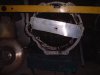
starter motor engine side, when I have welded the adapator plate on where it touches I will chop the old Rv8 housing up to make infills on the gaps (always good to use the same material if possible for strength). I will be including the section that the starter motor pinion lives in, photos due tomorrow once done.
Gap bed lathe, the bed is in two parts so you can remove the bed under the chuck for machining large parts, not you usual UK garage tool.
Regards Mark
Gap bed lathe, the bed is in two parts so you can remove the bed under the chuck for machining large parts, not you usual UK garage tool.
Regards Mark
Attachments

Question for Wanni
Cheers
Fred W B
Is this a material that you machine a part from, or are they supplied as a manufactured part?IGUS PLASTIC BUSHING
Cheers
Fred W B
Brett James-McCall
Moderator
Mark / Russ The flywheel weighs 9kg or 19lb for the English. The clutch is a Highly rated Toyota Diesel pressure plate and Kevlar 225mm which easily handles even the Toyota V8 so I do not think I will have any problems. Time will tell. I still have the cross section drawings I am sure so if you want a copy, I could email it. I also have not used any spacers, prfering to have the whole thing as a one piece affair. Also it all fits together in a standard fashion.
Brett James-McCall
Moderator
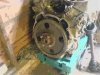
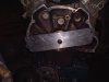
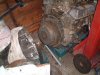
Okay, made my adapator today and welded on so looking good for now.
The adaptor is the front cut off my scrap Rv8 bell housing, milled down to 1" thick.
To align I got a piece of 1/16" ali, then drilled to the dowels on the engine block, then using a ball pein hammer gently tapped out the crank centre.
Bolted this to the adaptor and centred on the first motion shaft, clamped in place and welded up pic 2 (prior to welding).
With a 1" adaptor ring the first motion shaft on the box is long enough to fit inside the ring gear flex plate spacer so I am hopefull that I can just bolt the audi flywheel straight on.
NB/ welding was horrible.... the poor grade of cast material put ash on the TIG tunstun, even with the gas cranked up... never seen that before !
Once I have finished I,ll post a few more pictures.
Regards Mark
Attachments
Question for Wanni
Is this a material that you machine a part from, or are they supplied as a manufactured part?
Cheers
Fred W B
They have a huge catalog of finished bushing in several different mixtures of plastics, depending of the use you want to do with.
I do not know if the material is available in basic profiles.
Check attachment
Attachments
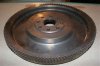
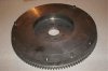
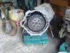
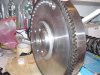
Okay, finished making my adaption for Audi to Rv8, cost next to nothing so you will have to excuse the scrap yard rust...... I will clean up before proper assembly.
I tried the RV8 flywheel but size killed this off so Audi flywheel bolted Rv8 auto TX spacer, turn down to suit and shortened.
I have drilled the flywheel to match the spacer, but will use the belt and braces appoach and bolt the out edge of the flywheel to the Rv8 starter ring plate.
The gearbox adaptor is 1" thick, when I removed the flywheel from the Audi block the front face was 30mm from the block, now I am done the front face of the flywheel is 55mm from the Rv8 block so its within a couple of mm to where it should be in the gearbox housing.
The whole lot is a couple of kg lighter than a Rv8 standard assembly but as the weight is closer to the crank centre it should spin up okay, bathroom scales give an all in figure, cover, driven plate, adaptors etc of 23kg.
Just hope it all works now, I think I may strap the engine down and fire up on the floor in the next few weeks to see how it all shakes !!! It should be okay as nothing that is balanced has been affected.
Attachments
Last edited:
Here is how I made my BMW fit an Audi 016. Some ideas to add to this pot.
One link is a photo page and the other is a MS Word document.
http://stweb.peelschools.org/sssweb/TTI-WEB/cars/pictures/BMWtoAudi/index.html
http://stweb.peelschools.org/sssweb/TTI-WEB/cars/Adapter Notes and Tips.doc
Cheers;
Jim
One link is a photo page and the other is a MS Word document.
http://stweb.peelschools.org/sssweb/TTI-WEB/cars/pictures/BMWtoAudi/index.html
http://stweb.peelschools.org/sssweb/TTI-WEB/cars/Adapter Notes and Tips.doc
Cheers;
Jim
Similar threads
- Replies
- 6
- Views
- 2K