Norfolk Tornado

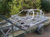
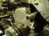
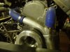
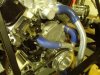
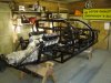
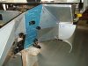
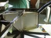
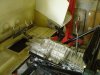
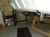
In an attempt to try and get the chassis finished, I wanted to re-design the rear clam mounting system. The Tornado design has a hinge bar that runs across the back of the car, which is visible below the rear clam. I wanted to a get rid of this feature and have a closer replication of the original design.

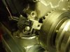
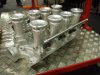
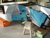
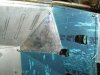
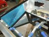
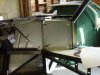
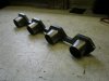
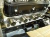
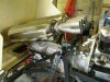
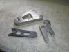
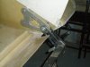
From some sketches I’d been given (thanks Brett), they were converted into CAD models and parts were then laser & water cut. The steel chassis brackets are cut from 4mm steel, whilst the body brackets and quick lift hooks are 12mm aluminum

The quick lift jack points have been designed so that they can be bolted in at a later date. A rear under-tray/valance will eventually hide the chassis currently left visible.

Regards
Andy
 

Attachments

  • P9261090.jpg
    P9261090.jpg
    45.9 KB · Views: 840
  • P9261093.jpg
    P9261093.jpg
    39.6 KB · Views: 886
  • P9261097.jpg
    P9261097.jpg
    41.5 KB · Views: 822
  • PA021090.jpg
    PA021090.jpg
    39.2 KB · Views: 898
  • PA021091.jpg
    PA021091.jpg
    34.6 KB · Views: 998
Andy,
Nice job, glad I could be of help with the drawings :) Will try to get up to Norwich to see you soon, but am pretty maxed out with work and Rugby for the next 6/7 weeks.

Brett
 
Well the chassis has finally gone to the paint shop. The process will be shot-blast, high zinc primer, high build primer, 2k gloss black. The picture is of the chassis on the way from blasting to the paint shop. Fortunately this was done over a few days of no rain!

Whilst waiting for the chassis to come back from the paint shop, I’ve been doing a couple of jobs on the engine. For the engine management system, a 36-1 trigger wheel has now been added to the TV damper. A recess was machined in the damper and three slotted holes were machined in the trigger wheel to allow for final adjustment. With the relationship of the missing tooth to the sensor established this can be finally mounted. The original front cover has the provision for a sensor mounting, but the UK sourced sensor is smaller & shorter, so it had to be modified to suit.

The alternator has also now been mounted. I originally mounted a brand new Lucas 17ACR unit I as a spare from a previous project, however as it was only rated at 34amp I considered this was to small (2 LP pumps, 1 HP fuel pump, electric PAS, ACU, ECU etc). Also what’s the point in trying for reliability and then fitting a Lucas alternator!

I’ve also started to mount the ignition coils to the cylinder heads. These are mounted on stainless steel adapters screwed into the spare tapped holes in the heads.

Next job is the ACU pump, but the engine needs to be fitted back into the chassis to work out the final position

Regards
Andy
 

Attachments

  • PA231094.jpg
    PA231094.jpg
    82.5 KB · Views: 918
  • PB011095.jpg
    PB011095.jpg
    39 KB · Views: 821
  • PB011097.jpg
    PB011097.jpg
    50.1 KB · Views: 777
  • PB011099.jpg
    PB011099.jpg
    44.9 KB · Views: 822
Although I don’t seen to have made much progress over Christmas, I’ve been pushing on with various parts. The chassis is back from the paint shop and the engine & trans is back in to start on the ACU mounting and the exhaust system. Brackets for brake calipers have been designed and are being manufactured. My IDA throttle bodies from AT Power, were shown at the Autosport Racing Car Show and I pick up the finished assemblies next week. As the bodies only came from the machine shop the Weds before the show, there was no time to assemble and flow balance them.

I’ve been debating for a while the best way to get the water back into the block when using a remote electric water-pump, as I didn’t want another bolted joint and any restrictions due to adapters etc.
In the end, I had the front cover re-machined to accept to 1¼.” aluminum spigot pipes, which are pressed & loctited into place. The internal bore is the same as the machined feed holes in the cylinder block, so no loss of flow or restriction. It’s also been machined to remove the old belt driven water pump (the original iron body pump is a whopping 7kg!),

These have been connected with a y-piece with two 1¼.” pipes paying particular attention to ensure that the flow is split evenly between the two. This then connects to a 1½” feed pipe, which I’ve used for the rest of the system. I think overall this provides quite a neat solution to the problem :thumbsup:

Regards
Andy
 

Attachments

  • P1151101.jpg
    P1151101.jpg
    53.7 KB · Views: 750
  • P1291104.jpg
    P1291104.jpg
    48 KB · Views: 741
  • P1291105.jpg
    P1291105.jpg
    42 KB · Views: 763
  • P1291107.jpg
    P1291107.jpg
    55.2 KB · Views: 861
  • PC281097.jpg
    PC281097.jpg
    58.2 KB · Views: 941
With the current rush interest in Tornado builds, I thought it’s about time I did a bit more on mine whilst I wait for the silencers to arrive. I’d started the panelling of the front end over 18 months ago, but didn’t finish them, as I didn’t want the chassis peppered with rivet holes prior to blasting. I ended remaking a couple of the panels, mainly as my skills improved over the project and my desired level of acceptability had also increased.

My panelling around the front suspension differs from the Tornado manual and I believe gives a neater overall finish, with the final panel (triangular panel) covering the edges of the 3 other panels. Also instead of using an extrusion to cover the edge when 2 panels come together I’ve allowed approx 10mm on the edge of the panel and then wrapped one panel over the other.

A few of the panels will have stiffening ribs in them. This will be mainly cosmetic, but also prevent drumming. Finished panels will be powder coated satin black and then fitted with black 4mm rivets.

Final photo shows the installed Active Technologies throttle bodies on the engine.

Regards
Andy
 

Attachments

  • P3281167.jpg
    P3281167.jpg
    52.9 KB · Views: 749
  • P3281168.jpg
    P3281168.jpg
    50.5 KB · Views: 701
  • P3281170.jpg
    P3281170.jpg
    56 KB · Views: 698
  • P3281171.jpg
    P3281171.jpg
    47 KB · Views: 705
  • P3281173.jpg
    P3281173.jpg
    61.9 KB · Views: 831
Andy:
I've been looking at the Active Power setup, seems lower than the Dynatec setup and I would worry more about performance than the setup looking like a set of Webers. The Active Power setup actually appeals more to me. What management system are you using with those throttle bodies?
Your build is really coming along well.
Cheers
Phil
 
Andy,
I have been looking at your water pipes on the front of the engine. I think you have done a superb job. I used the braided lines for mine with the bungs welded to flat stock and using the original bolt holes. I may revisit them and go with the pipes also. Using a lower flow pump would seem to shout for lower restrictions.
I have one comment though. On your last pic of the pipes I noticed an air-conditioning compressor in the background. It doesn't look like there is enough room for the belt to go to the right side of the engine between the pipes. Probably just the angle of the photo.
Seeing your pipes set up reminded me that many of the setups haven't given a thought as to how the water would be emptied if the time arose for that. I put a 6 AN hose on my lowest pipe in the engine bay. That way when the time arises it is a simple matter to open the plug on the fitting and catch it without it going all over the place.

Bill
 
Hi Guys,
Many thanks for the words of encouragement.

Phil,
I plan to use an ECU called Typhoon from Specialist Components. I posted some info on this under the vendors section as a follow-on to the info on the throttle bodies.

Bill,
The AC belt does go between the two water pipes, without any foul issues. The parts were quickly mocked up for the photo. I like you idea of adding a drain pipe instead of just pulling off a pipe. I also liked the way you mounted your alternator, as mine (& the alternator) are mounted in a similar way. It’s sharing ideas like this that make this forum so great.
Regards
Andy
 
With the front end panels now finished, I’ve been playing with my birthday present; a home powder coating kit from this company:

http://www.electrostaticmagic.co.uk/

The results are far better than expected and I’ve managed to do all the wheel arch panels in an old domestic oven. I did try curing the panels between a pair of halogen heaters, but I couldn’t get it up to the correct temperature (it needs 180°C for 10 mins & I could only achieve 110°C). So I’ve either cost to make a large enclosure to minimise the heat loss or send them out to a local company I’ve previously used

Closure panels to seal the fuel filler necks from the cabin area (to meet IVA requirements) have also been made. It’s easier to do at this stage whilst there’s easy access into this area. The forward panel will be riveted in place, whilst the rear panel will be made removal using M5 captive fasteners

Regards
Andy
 

Attachments

  • P4101180.jpg
    P4101180.jpg
    50.8 KB · Views: 1,159
  • P4101182.jpg
    P4101182.jpg
    42.8 KB · Views: 760
  • P4101183.jpg
    P4101183.jpg
    43.8 KB · Views: 797
Andy,
You might want to try and get the filler pipes pieced into place before you seal off that area. I used rivnuts on mine just so I could get to the area if I had to drop the tanks(which I have had to do more than once). You can then either put sound proofing(behind) or carpeting over the panel. If you plan on a stereo, the speakers will work pretty good there also.

Bill
 
Hi Bill,

Thanks for the feedback. The rate I’m progressing, it will be years before anything is permanently attached to the chassis. The next bit to do in this area is the mounting of the fuel caps & filler necks and then I’ll see what room is left for insulation. I’ll probably powder coat these panels black, as they are high up behind the dashboard. In fact I’m considering only having carpet on the floor & rear bulkhead & the remainder in satin black powder coat

Regards
Andy
 
Morning Andy,

Looking good mate, glad to see your painting panels black like the real deal. Mine will be 2 pack black with matched spray cans for touching up what i call tool slippage!

I have completed rear end and am now working on closure panels to front & preping spyder.

Cheers

KarlB
ps drove mates lotus exige yesterday for first time ......lovely balance, lovely car.
 
The new silencers I’ve designed and previously posted about have now arrived and I’ve started the mounting of them. The collectors (these are standard Edelbrock parts) have been bolted to the silencers, so I can easily change the silencers if required and the overall length minimised to allow more room to package the primary pipes into the collectors.

As well as the rear mount, a front mount has also been fabricated as I don’t want the weight of the silencers been taken by the primary pipes. This has a rubber isolator bush built into the lower fixing to provide some damping into the system. The tie-rod on the rear mount is a simple way of putting maximum longitudinal stiffness into the bracket with minimum weight penalty.

I had a pair of header flanges laser cut by a local company from 10mm steel (Probably a bit too thick, 8mm would have been OK) and I made up some stub pipes to convert from the rectangular port to the 1¾” tubing I plan to use for the primaries. The really annoying part is that I’d hand carried from the US a pair of Edelbrock header flanges, but they don’t fit their own heads!

All I have to do now is join up the two :laugh:

Regards
Andy
 

Attachments

  • P4251185.jpg
    P4251185.jpg
    40.7 KB · Views: 688
  • P4251186.jpg
    P4251186.jpg
    48.9 KB · Views: 705
  • P4251188.jpg
    P4251188.jpg
    53.7 KB · Views: 711
  • P4251189.jpg
    P4251189.jpg
    45.3 KB · Views: 736
Andy, You do know you may have to cut your flanges into "singles" don't you? you'll never get the headers on and off if they are the correct "bundle of snakes"

Simon
 
Hi Simon,

This had crossed my mind, but I've seen others use one-piece flanges with cross-over pipes. I can always get the hacksaw out later........

Regards
Andy
 
Back
Top