S2's Build Thread

View attachment 124982
Scott, I have one observation - I believe the the pedals were designed to push a master cylinder that's mounted either level with the balance bar or angled downward from the balance bar so that as the pedal moves forward, the arc of the balance bar pivot point continues to move the master cylinder pushrod forward. It looks to me like the angle of this iBooster pushrod won't work as efficiently with a floor mounted pedal. Theoretically (in my mind), as the pedal moves forward , the pedal's pivot point is moving down and away from the master cylinder and it will no longer be moving the master cylinder pushrod at the same rate and will actually by applying force downwards on the pushrod. Seems like a hanging pedal would work better with the iBooster mounted at this angle because the arc of the pedal's pivot point would then be going upward as it nears the end of its travel.
 

Scott

Lifetime Supporter
Scott,

You are correct and I've been looking for a solution. I considered using hanging pedals, but there are challenges doing that in an SL-C and I didn't spend much thinking about it. However, I figured out that if I removed the mounting flange on a GEN1 iBooster, ground the cast aluminum body and rotated the unit, I could obtain the optimal position (i.e., the input rod at the same height as the stock master cylinders and parallel to the floor). This resulted in the reservoir inlets pointing down (i.e., below the horizontal). The master cylinder has two bolts, so it's easy to rotate it 180 degrees which results in the reservoir inlets optioning above the horizontal, but not straight up. The picture below shows the optimal orientation. The visible ports on the left are the pressure ports and the two black rubber rings on the right are the reservoir ports.

1684617164161.jpeg


I designed a new bracket which is more compact and lowers the CG. However, I had issues bench bleeding the iBooster, so I tilted the unit so that the reservoir inlets pointed straight up and I was able to get them bled. I don't know if there would be an issue with a bubble forming after it was installed in the car or not. If anyone has thoughts on that, let me know.

I think the next step is to machine an adapter that rotates the reservoir inlets to the vertical. That should be easy to do, but I'm concerned that it might confuse the travel sensor / ECU. If so, I might need to figure out a way to extend the input rod.
 
Glad to hear there was a solution for that, I figured hanging pedals wouldn't be an easy option. I think you've solved the issues. Doesn't seem like air could be re-introduced to the MC from the reservoir once the MC is bled. Also doesn't seem like the electronics would be affected by the orientation. Wouldn't that be a safety concern? Anyway, I'm loving the build.
 

Scott

Lifetime Supporter
Having finished the X-pipe and oil inlet heatshields, the starter heatshield was next. However, when I went to install the starter, it collided with the catalytic converter.

1686662200922.png


How the F did that happen? Not the first time that something was overlooked because I didn’t have all of the relevant parts in place when making decisions. In a previous post I used a rotary table to machine the starter’s mounting flange to clock the starter to its maximum, so I thought I was screwed. The only solution would be to machine the starter’s gear reduction housing which, if possible, would result in the top bolt being captured between the mounting flange and the housing. Not ideal, but workable. So, I popped the starter apart and determined that I was in luck. There are isolated cavities on the left and right of the cavity that contains the gears. This allowed me to machine a notch for the captured bolt (the problem at hand) as well as drill and tap a hole to support the heat shield. Once that was done, I repeated the process of machining the mounting flange to further clock the starter as described in this post.

1686662282729.png

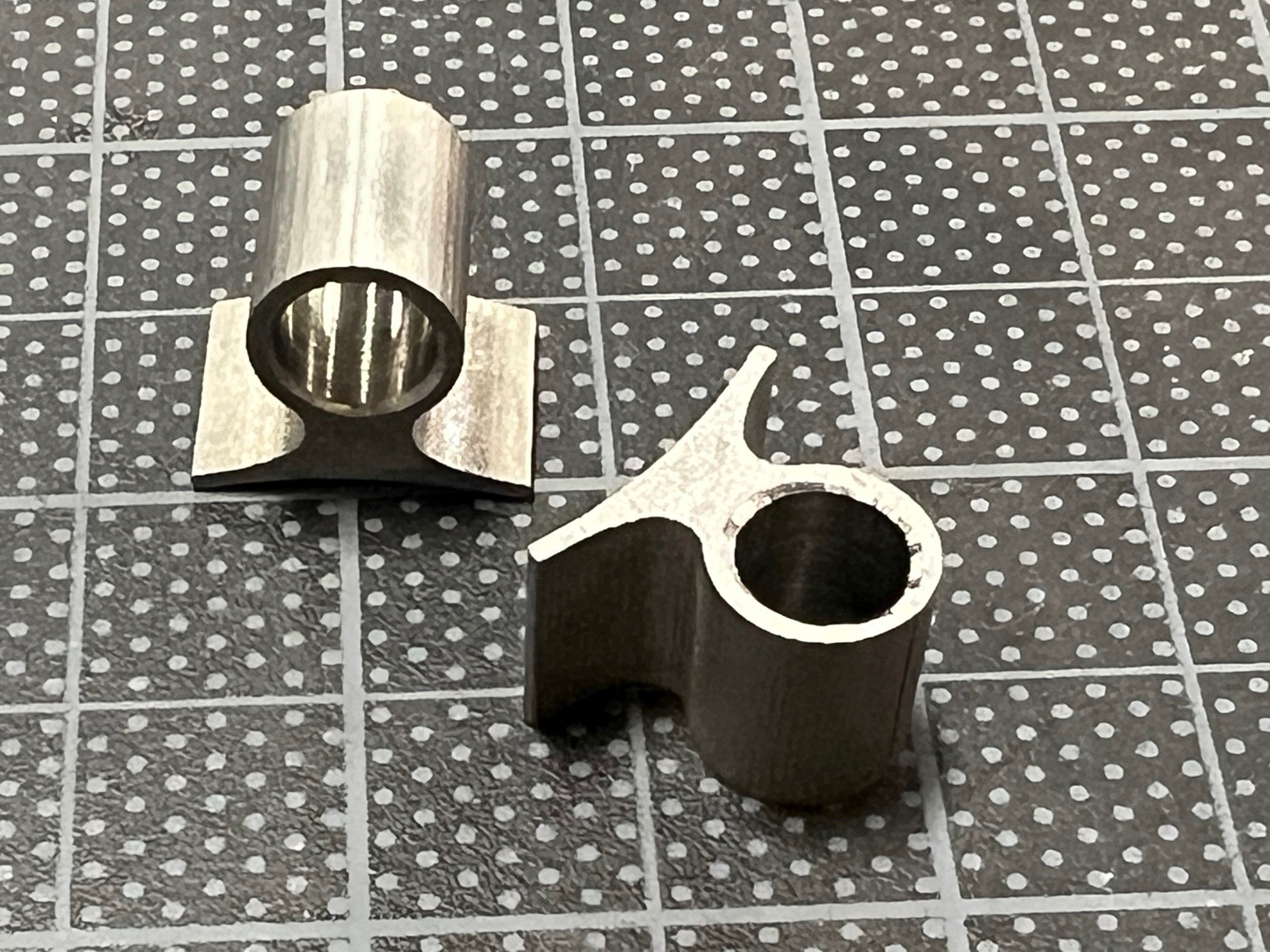
The cavity on the right will be notched to accommodate the head of the captured bolt and the cavity on the left will be drilled and tapped to provide support for the heat shield

While the starter/catalytic converter collision was a very unpleasant surprise, the reality is that I would have wound up in the same place even if I had noticed the issue before fabricating the cat-back system. That said, you really want to know that you can get out of a hole BEFORE you fall into it.

As is typical in a SL-C, everything was really tight and it took me a while to figure out how to design the heat shield. Part of the challenge is that the mounting flange is cantilevered at a 15-degree angle resulting in the assembly constantly falling over while I was that trying to take measurements. After much frustration, it occurred to me to 3D print a jig to hold it at the correct angle… yeah, that made a big difference.

1686662328065.png

Starter mounted to a 3D-printed jig (top), miscellaneous scrap shims (left), feeler gauge (center), digital angle finder (right) and mock 3D-printed bend profile (top right). Note the modifications to the starter; a notch has been machined into the top to accommodate the captured bolt and a hole has been tapped on the right side to support the heat shield.

I have found the following useful when measuring awkward items. Scrap shims of various thicknesses combined with a feeler gauge. Just make sure that you debur the edges of the shims so that they sit flat. A digital angle finder is also very useful — Abe has a manual one, but he borrows my digital one a lot. It measures to one tenth of a degree and there are buttons to zero it and to display the reverse angle which means that you don’t need to do any math. It’s well worth the $16. I also 3D printed narrow sections of the bend profiles to fine tune clearances. For example, the thin black piece in the upper right of the picture above is the profile of the main shield and a welded mounting arm.
Like the other heat shields, this one required me to learn a few more sheet metal tricks:

Tutorial:
I spent a little over two hours watching a tutorial on Solidworks sheet metal features; 80% I knew, 10% showed me how to do certain things better, 5% was completely new and 5% was irrelevant to my use case. The high-end CAD packages have a lot of advanced features and it’s worth spending a little time and money to access quality online training.

Unfold and Fold Features:
For the last two heat shields I was able to use Solidwork’s Corner Relief feature to ensure that bending wouldn’t deform the corners. However, no matter what I tried, SendCutSend rejected several of the bends because it didn’t like several of the corner reliefs. The solution was to use the Unfold feature to flatten the problem flanges, add extruded cuts to the problem corners, and then refold the flanges via the Fold feature. Problem solved.

Closed Corner Feature:
Once the bend radius and K-factor are set for the type and thickness of material, the software automatically calculates the bend allowances which is great. However, I had several areas where after making several bends the material bent back onto itself and I wanted to ensure that the gap was tight enough to be welded. Fortunately, Solidworks has a Closed Corner feature that does exactly that. You simply click on the two edges that you’d like to “close,” specify the desired distance between those edges, and then choose one of three options; (1) butted, (2) edge A overlapping edge B or (3) edge B overlapping edge A. SendCutSend specifies 15 thousands as the minimum tolerance which worked out great.

In the picture below, the feature is closing the corner between the two blue edges. The yellow part showing how one of the flanges is being extended. The second flange remains unchanged because I had specifically trimmed it in a previous step, but in many cases both sides are extended. You can also see the left most (i.e., butted) of the three options is selected and that the distance is 15 thousands of an inch.

1686662425834.png


1686662456403.png

It would be extremely difficult to figure out all of the bend allowances and closed corners without CAD. The curved line on the right is the final shape, but that flange was extended to provide a parallel edge to the bending line allowing it to be pushed in the CNC back stop. If you look closely, there are small bridges on the curved portion to facilitate removal post bending.

Multi-Body Part:
I have been aware of the multi-body feature for years, but I never used it. My workflow was to design separate parts and combine them into an assembly to ensure that everything fit. This works, but you have to update the relevant dimensions in multiple files and you have to mate everything in the assembly. I have used external global variable files before, but that takes a little effort.
With a multi-body part, you basically design other parts in the same file. This allows those parts to be parametrically driven by the first part. There is no need to update the dimensions in multiple files, no need for an external global variable file, and no need to mate the parts in an assembly. I wouldn’t do this with all of my parts, but in the right situation it really simplifies workflow.

Part too Small:
One of the parts was rejected by SendCutSend because it didn’t meet the minimum size for bending. The solution was to extend the part to meet the minimum size and to add bridges to make it easy to remove the excess post bending.
The heatshield involved four laser-cut pieces, one hand-cut piece, ten CNC bends and two spacers fabricated on the lathe. The bends were perfect, but when I went to install it I didn’t have as much clearance as I wanted, so I cut a 45-degree corner into the bend with the red line below and then welded a piece into the gap.

1686662500293.png


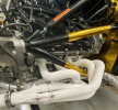
The heatshield is solidly mounted at three points; the arm that connects to the lower flange bolt, the tapped screw in the front face of the starter’s casting, and the tab (purple) that was added to the long bolt in the back of the starter. It is solid enough that the assembly can be lifted by the heat shield.

The starter was easy to take apart, but I couldn’t reassemble because it needs to be compressed. So, I took it to a repair shop. When, I decided to add a mounting tab to the rear bolt the starter’s halves separated on that side and I couldn’t get it back together. So, I made a second trip to the repair shop. If you’re going to remove that bolt, ensure that you tightly clamp the starter in a vice before doing so.

1686662532246.png

Heatshield (left) and starter (right). The arrow points to the rear mounting tab and spacer. You need to clamp the starter when loosening the long bolt to install the rear tab or you’ll be visiting the repair shop to get things put back together.

1686662564981.png


1686662579765.png


1686662603475.png


Three heat shields down, nine more to go.
 

Scott

Lifetime Supporter
In a previous post I modified the stock fuel tank to convert it to a FIA-compliant fuel cell. The challenge is that to replace the bladder in a SL-C with a tub you must; remove the windshield, center body, cage, seats, tub and fuel tank close out panel. That’s a lot of work, especially given the amount of sealing that needs to be redone. For this reason, I designed the fuel cell so that the bladder can be removed from the bottom of the car. As can be seen in the picture below, this leaves the access plate and center section of the bladder unsupported.

1687012722879.png

The bladder is removed via a hole in the bottom of the car which requires the bladder to have removeable support structure

To support and protect the bladder I fabricated a bolt-in structure from rectangular tube and 1/4” plate. To get a good fit I took careful measurements and ordered a chipboard prototype from SendCutSend. Even though the piece was large, roughly 24” x 10”, it only cost $6.29. After laying it on the fuel cell I tweaked a few measurements and ordered the final aluminum part.

1687012749006.png

The center oval plate is lower that the rectangular plate to accommodate the thickness of the access panel and gasket. The oval ring provides clearance for the bolt heads on the access panel.

1687012786129.png


1687012804306.png

Bladder support structure installed. Note that only a few of the bolts are installed in the access panel.

The next step was to add a thin cover plate to the bottom of car. I couldn’t figure out a good way to use quarter-turn fasteners, so I went with screws because the panel should only be removed every 5-7 years. Drilling and taping 22 holes on the underside of car was tedious.

1687012834355.png


While I was finishing up the fuel cell, I considered using Holley’s recently released LiDAR-based fuel level sender, but it can’t see through foam. That would have required me to cut a full-height hole in the foam and insert a porous tube to ensure that the foam didn’t obstruct the device. While this would have worked, the primary purpose of the foam is to prevent a flame front from forming. I assume that’s a small risk, but it felt antithetical to one of the key safety features, so I replaced the stock fuel-level sender with a high-quality one commonly used in aviation.

Although the bladder is tough and the fuel cell is very-well protected in a SL-C, there are two simple precautions to reduce the chances of the fuel-level sender puncturing the blader; (1) a bend was added to the tube in a location indicated by the manual and (2) a nylon foot was machined on the lathe and press fitted on the tip of the sender.
 

Scott

Lifetime Supporter
I was looking for a local shop to form some panels and discovered Back Bay Customs which is about 60 miles north of Boston in Portsmouth NH. After seeing one of their cars in Boston, I spoke with Adam, the owner, and decided to haul my car to the shop. I’m very picky about my car and I was pleased to see a large tidy shop, lots of metal forming equipment, CNC plasma table, paint booth, and multiple fabricators. I’ve been very pleased with their creativity, fabrication skills and communication.

The first project was the upper firewall. Sealing this area for heat, sound and vapors is critical and the stock firewall left a fair number of gaps, so we decided to replace it. Adam noticed that the firewall wouldn’t sit flat on the traverse 2” x 6” chassis tube. WTF?

The issue was that the two mounting brackets for the rear hoop legs weren’t coplanar with the 2” x 6.” One was 1/8” forward and the other was in excess of 3/8” forward which resulted in the top of the firewall tilting towards the cockpit while also imparting a left-to-right twist. This looked like ass and made it impossible to get a good seal. The solution was to cut off the brackets, grind the hoop smooth, fabricate two different brackets to account for the variance in offsets and weld everything.

1689870871630.png

Replacement brackets welded in place. Notice that the left bracket projects further than the right bracket

The next step was to fabricate a blister to accommodate the induction tube which projects into the firewall. To fabricate the curved corners, Adam made a paper pattern, cut and annealed 1/8” 5052 sheet, and then used a soft mallet and a slapper to stretch it over a post dolly. During the shaping process he had to anneal the sheet several more times to keep it soft. He then trimmed the shaped piece to match the pattern, tweaked the middle section and welded it together.

1689870912678.png

From left to right; soft mallet, slapper, profile gauge, and post dolly

1689870944975.png

Blister mocked in place

1689870978043.png


1689871011647.png


Once all of that was done the firewall still had too much flex which was remedied by welding tabs to rear hoop’s upper radii. This is particularly important because most SL-Cs, including mine, mount a large coolant expansion tank to the upper firewall.

1689871032427.png


1689871049689.png

Firewall support tab tacked to the rear hoop

The cage is nicely fabricated and serves its primary structural/safety purpose well. However, it falls short in multiple areas which result in either unnecessary compromises or a lot of work for the builder:
  • The front hoop doesn’t fit the body well which impairs vision and results in massive A-pillars. I fixed that issue in this post. Given the large number of SL-Cs that have been produced, RCR should have started CNC forming the front hoop long ago.
  • Perhaps it’s just my car, but there’s no excuse for the issues with the rear hoop leg brackets. It was downright sloppy. There should be a jig to ensure alignment and a quality check before the car ships.
  • The small tabs in the upper corners should be stock. While this is a trivial fix, not all builders have easy access to welding equipment and it’s a shame to wreck the nice power coat finish that comes from the factory.
 
I got this oil filter from Billet Connection. The primary benefit is a see through window which enables you see any particles trapped in the 60 or 115-micron stainless filter (smaller particles pass through and are filtered via a standard disposable filter). This is achieved by connecting an air or Co2 source to the integrated Schrader valve to clear the oil between the window and the stainless filter. It also has a bypass feature should it become completely clogged and a nice mounting bracket.

http://www.billetconnection.com/cvf_page.html

IMG_0366.JPG


IMG_0369.JPG


IMG_0370.JPG


IMG_0371.JPG
found the perfect compliment to this remote oil filter mount-
 

Attachments

  • cantons-billet-oil-filters.jpg
    cantons-billet-oil-filters.jpg
    1.1 MB · Views: 103

Scott

Lifetime Supporter
To optimize cooling, it’s imperative that all air that flows into the radiator inlet in the body is forced through the condenser and radiator. This is best accomplished via an air-tight, diverging duct that provides a smooth transition from the opening in the body to the outer edges of the radiator core. Specifically, it’s preferable that the air isn’t allowed to contact the underside of the nose, the vertical panels that support the radiator nor the radiator’s side tanks.

There’s a fair amount going on inside of the duct; condenser lines, nose hinges, splitter support rods and a tow hook, so it took a while to figure out the best approach. The first step was the top of the duct. The triangular section of the nose subframe was designed to pitch downwards from the top of the radiator to the top of the inlet in the body. It stiffens the subframe while providing a robust mount for the top of the inlet duct and the tow hook (the car be jacked on the car on tow hook). The top of the duct was made from four parts:
  • Two triangular inserts.
  • A cover between the nose subframe and the radiator.
  • A cover that is attached to and pivots with the nose. When closed, it seals the body to subframe.
The video below shows prototype parts and the pivoting motion.

1694297310804.png

The triangular inserts sit on flanges covered with thin strips of rubber (not shown)

1694297328542.png

The triangular inserts were formed using custom dies. They were cut from 1/4” steel plate on a CNC plasma table, the edges were dressed with files and a pencil belt sander, the panels were annealed in the areas to be shaped and a hydraulic press was used to emboss the shape.

1694297354523.png

A closeout panel was fabricated to seal between the nose subframe crossbar and the top edge of the radiator. It also seals the top of the condenser.

It was tempting to use the vertical panels that support the radiator as the sides of the duct, but they’re not well suited for that purpose. They’re several inches wider than the both the inlet and the radiator core which will result in the air expanding beyond the radiator core, colliding with the nose hinge standoffs and hitting the radiator side tanks head on. This makes it more difficult to seal the sides of the radiator, increases drag and I assume has a deleterious effect on mass airflow through the radiator core. Since the pivoting half of the nose hinge is bolted to the side of inlet in the body, the ideal location for the duct side is between the fixed and pivoting halves of the hinge. The issue with that approach is that the hinge would bind. The solution was to manually machine a 0.062” pocket into the fixed half of the hinge to accommodate the side panel.

1694297392238.png

0.062” pocket machined into the interior face of the stationary part of the hinge. Note that the leading and top edges were left full thickness which facilitates air tightness and maintains aesthetics. It would have been a lot easier to design this pocket in CAD and have it CNC’d, but it came out great.

1694297413430.png

The splitter support rod tabs that had been welded to the subframe last year interfered with the top of the duct. Fortunately, they were only tacked into place so it was easy to cut/grind them off and fabricate a new set that cleared the duct.\

Unlike the stock radiator which has very little in terms of vibration isolation, the custom radiator is supported via two rubber sandwich isolators per side. To maintain this level of isolation foam was used to seal the top and bottom of the duct and rubber flanges were used to seal the sides.

1694297437662.png

The stock vibration isolators (left/black) are small grommets and are next to useless. The custom radiator uses sandwich isolators (right/red) so it’s important to ensure that duct is properly isolated from the radiator and condenser.

1694297463554.png

An adjustable rubber flange (black) is notched around the condenser lines and is used to seal the sides of the duct to the face of the radiator while keeping the two isolated. The top and bottom are sealed with foam strips.

1694297487868.png


Scott

Lifetime Supporter
The heat shield for the induction tube was fabricated from 0.062” 5052 aluminum sheet and two pieces of aluminum tube. I’ll add reflective foil to the hot side in the future. I’m halfway through the heat shields, six completed and six more to go.

1694963232239.png


1694963246897.png


1694963258582.png
 

Scott

Lifetime Supporter
The heat shields that protect the chassis from the headers are finished. They were complex because the stock 2”x 2” chassis rails aren’t parallel nor co-planar and, complicating matters, I scalloped four of the chassis tubes to accommodate the headers. In addition, there were several hoses in the way. Fortunately, the guys at Back Bay Customs are excellent fabricators. The left side is a single piece and the right side is two pieces to accommodate the dry sump filter and lines. Everything is removeable with the engine and headers in place.

1696687692298.png

The chassis tubes were scalloped in previous post to accommodate the headers.

1696687716973.png

Paper and tape were used to make templates

1696687734963.png


1696687746040.png


1696687755916.png

The heat shield conforms to the scalloped 2” x 2” chassis tube. 1/8” shims were welded to the back side of the heat shield to provide an air gap between it and the chassis tubes. There is a small heat shield mounted to the engine block to protect the back of the alternator.

1696687778858.png


1696687789824.png
 

Scott

Lifetime Supporter
To improve the serviceability of the tail subframe I sectioned the 1/2” tube in two places. However, the smallest tube connector I could find was for 1” tube. I considered machining them, but I need four and each requires multiple lathe and mill / rotary table operations. Given that my standards are much higher than my machining skills, I decided to have them CNC’d. This allowed me to add some nice features; (1) a chamfer for the weld, (2) boring of the section that inserts into the tube to reduce weight, and (3) tolerances that capture the nut which removes the need for a wrench.

1698806259874.png

Two symmetrical tube connectors

I’ve used Hubs to CNC parts in the past so I uploaded the CAD model and selected 4140 alloy, “as machined” finish, and economy offshore (23 business day delivery). `The prices below are for a single part (i.e., half of a set). As you can see, the unit economics for CNC machining is radically different than 3D printing or laser cutting.

Quantity Unit Price:
1.........................$107.21
2...........................$71.73
10.........................$22.35
1,000......................$1.15

This is due to the need to generate the G-code for the first part and potentially the need to fabricate custom fixturing, which this part didn’t require. These unit economics influenced the design. I had considered an asymmetric design in which the half with the socket head cap screw was different than the half with the nut, but that would result in two different parts and half the quantity. Since there was only a small aesthetic difference for a hidden part, I went with a symmetric design.

The screen shot below shows the pricing difference for 10 pieces (i.e., 5 pairs) for on/off shore and different lead times.

1698806299453.png


1698806315542.png

I’m very pleased with the quality

1698806359369.png

Chassis tube sectioned and tube connectors ready for welding.

1698806398214.png

The part geometry captures the nut so no tools are required on the back side
 

Scott

Lifetime Supporter
I’m finishing that last couple of items on the headers and catalytic converter assemblies before I have them ceramic coated. The headers and merge collectors have double-slip connections which are typically secured with springs similar to the one shown below.

1699030122507.png


Instead, I used these cast stainless steel mounts. Note that the bottom flange is radiused to better fit the exhaust tube’s outside diameter.

Merge+Collector+Cast+Mounts.jpg


1699132329521.png


The mounts are connected via a 1/4” bolt. After the coating is finished, the nuts will be replaced with jet nuts tightened just enough to prevent rattling. While they will allow less expansion than springs, double slip joints don’t move much and retention is more for safety than anything else.

The O2 sensors were added to the catalytic converter assemblies. These saddle-style cast stainless steel weld bungs are a lot nicer than the standard ones because the flange is curved to match the OD of the exhaust tube. They are available from Vibrant Performance.

Cast+Weld+Bungs+01.jpg

The short boss on the back side matches a standard hole saw which results in a clean, self-jigging fitment

1699030358604.png

The saddle-style flange fits the OD of the cone well.

The next step is to have the headers, cutout tubes and catalytic converter assemblies ceramic coated.
 

Scott

Lifetime Supporter
Brian,

After a lot of research, I'm going with Zirotec's patented ThermoHold coating. Most ceramic coatings consist of ceramic chips suspended in a polymer. They are applied with a spray gun and then baked (Zircotec also offers a lower-performance coating like this). ThermoHold is more akin to welding than painting. After a series of preparation steps, zirconia ceramics are plasma sprayed using a water-cooled gun while the part is shieled with argon. This results in a 0.3mm thick layer with lots of small pockets which further reduces heat transfer. Note that aerogel, the best known insulator, also utilizes air pockets to achieve it’s amazing insulation properties (it’s the lightest known solid, because it’s mostly air). Unlike the smooth polymer-based finishes, ThermoHold has a texture similar to 220 grit sandpaper and can only be removed by grinding it off.

1699141775855.png

Robotic arm plasma spraying ThermoHold

The underlying coat is Performance White and is good to 1,400 °C (2,552 °F). You can then optionally add a color coat which is good to 900 °C (1,652 °F). I’m thinking of Performance White or Antique Silver which reminds me of what Harmon Kardon used to call a champagne finish. I'm bringing them to the UK on Sunday night, so I need to make a decision. Thoughts on color?

1699139733171.png

1699141099582.png


1699140500576.png


I think Antique Silver is one in on the right.
1699140666059.png
 

Attachments

  • 1699141100100.png
    1699141100100.png
    2.4 MB · Views: 45
Last edited:

Brian Kissel

Staff member
Admin
Lifetime Supporter
Wow, as with everything on this build, that’s top of the line coating. With all the plasma spray technology here in the states, no one has the capability here ?
I like both colors you have chosen, and also the aluminum metal one. But the antique silver may hide things better, because of it being darker. Because of the coarseness, how do you probably clean them ?

Regards Brian
 

Scott

Lifetime Supporter
With all the plasma spray technology here in the states, no one has the capability here?

Brian, IMO Zircotec offers the best solution for my use case. They have pedigree in motorsports including F1 and halo/supercar OEMs, a patented coating and significant intellectual property around the process. They have a rigorous preparation process that include washing with a strong detergent, sand blasting and applying a metallic-based bond coat. ThermoHold is then sprayed at temperatures well in excess of 10,000°C (18,032°F) at nearly twice the speed of sound. The size and layering of the particles creates air pockets which reduces heat transfer. The process is highly sensitive to power fluctuations which lead to them having their own power substation. According to their website:

There are a large number of parameters that influence the interaction of the plasma-spray feedstock with the plasma jet and the substrate, and these parameters can result in very wide variations in the final product (e.g. feedstock type and composition, feed-rate, plasma gas composition and flow rate, energy input, torch geometry, nozzle design, nozzle offset distance and substrate cooling). The Zircotec process ensures that these parameters are tightly controlled within pre-defined set points, thereby providing control over the quality of the final product.

The biggest downsides are cost and that you need to ship the parts to the UK. I’m located in Boston and I was terrified that they might get lost or damaged during shipping. Fortunately, I was able to freeload a ride and pre arrange a faster-than-normal turnaround. I dropped them off after I landed on Monday and picked them up on Friday. They got a white-glove transport service.

1699740697146.png
 

Brian Kissel

Staff member
Admin
Lifetime Supporter
Thanks Scott . They are getting treated better than I do. First class ride for a first class build.
Congrats !!
Regards Brian
 
Back
Top