
Great progress Bob..........Looks great!

You are using an out of date browser. It may not display this or other websites correctly.
You should upgrade or use an alternative browser.
You should upgrade or use an alternative browser.
I just got a title for my GT40 in Texas. It was totally painless, although the supervisor had to go read all of the rules since they don't do this very often to say the least. We now have a law that states if a car is built as a replica, it can (or should be) titled as the car it replicates with the wording "replica" on it.
Mine is now a "1966 TSC GT40 REPLICA". I had to have the MCO, the invoice (to pay taxes), and the rubbing of the chassis VIN number.
Registration is the next step, but I will wait until it is running and I have insurance on the car. I ordered my personalized plates now though. I got "66GT40".
I am quite happy that the title says 1966 GT40 since now I can get insurance for a 1966 car and when I take it to be inspected, they only go by what the insurance policy says and therefore I have to meet 1966 rules. I was originally worried because they were telling me it had to be titled as a 2014 assembled vehicle and meet 2014 regulations.
Yea!
-Bob Woods
Congratulations Bob.
Congratulations Doc!
:thumbsup:
:thumbsup:
Darrin,
I'm sure it will. I think it was their first time for a replica. Just keep after them until they read the rules.
They will have to title it just exactly as it is on the MCO. Mine said "1966 TSC GT40 replica". I would have preferred "1966 Ford GT40 replica". If you have a choice, get the MCO to say what you want. You can get the title anytime with the MCO, receipt, and the VIN rubbing. Do it now, you can get the registration later.
The key is that insurance will list it as it is on the title and the inspection station will go by what is on the insurance card. You do not want at "2014 assembled vehicle".
-Bob Woods
Darrin,
The MCO does give the VIN number. My VIN number was a plate welded to the back of the frame with the numbers stamped on a sheet of steel. The rules require that you bring a rubbing of the VIN.
Call or e-mail me for more details if you don't have a VIN. I would like to come over and see your car anyway.
-Bob Woods
There has been a lot of discussion about fuel pumps and associated systems for fuel injection. See "Simple fuel systems" and "Getting fuel from both tanks with one pump" under the "Fueling, Electronics, and Engine Cooling" forum. Some of these seem very complicated and I'm not sure that they are completely necessary.
I have some experience with fuel injection and hydraulics and I am aware of cavitation and vapor bubbles running around the fuel lines. I think that my proposed approach will work without problems.
First of all, realize that the Tornado fuel tanks have a baffled section at the rear of the tanks that is foam filled. The lower fitting has a pipe on the inside that goes to the bottom of the tank.
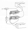
My plan is to build two large tees, one for the suction from the tanks and another for the fuel return to the tanks. The tees are 1.5" square aluminum tubing. The suction tee will go to both tanks and hence the two tanks can self-level since they are continuously connected. This might slow down the filling at the service station since I anticipate that there will be a delay in getting from one tank to the other. I can either fill both sides or be very patient. In either case, I'm not sure that I will ever need to have both tanks completely full. In town I don't need the extra weight and on a road trip, I can just stop after a few hundred miles. The fittings on the tank are -6 and I wish they were -8 for the suction for sure and maybe for both to keep the velocity low in the hoses, but I will see if this works.
The suction tee will then go to the inlet of the high-pressure EFI fuel pump. I will orient the exit from the suction tee on the top so that it will draw out any air or vapor that might form in the tee (even though it is drawn on the side in the illustration). From the pressure regulator on the fuel rail, the return flow will go to the return tee and then to both tanks. The flow rate and hence the velocity of the fuel hitting the foam will be reduced compared to a full return to one tank.
I will have a coarse pre-filter on the suction side and a normal high pressure fuel filter on the outlet of the pump. I could put an adjustable valve on one of the return lines if the return flow doesn't balance automatically because of the common connection at the bottom of the tanks.
I have made compartments on both sides of the engine under the rear sill covers. The sill covers are removable. This way, the tees, pump, and filter are out of sight and the suction tee is at the same height as the bottom fitting on the fuel tanks. The suction and return lines will go around the bottom of the rear bulkhead on the engine side, either above or below the cooling tubes. The return line from the EFI fuel rail will go from the engine below the rear sill cover in the gap between the sill cover and the bulkhead.
Anyone else done this? See any problems?
-Bob Woods
I have some experience with fuel injection and hydraulics and I am aware of cavitation and vapor bubbles running around the fuel lines. I think that my proposed approach will work without problems.
First of all, realize that the Tornado fuel tanks have a baffled section at the rear of the tanks that is foam filled. The lower fitting has a pipe on the inside that goes to the bottom of the tank.
My plan is to build two large tees, one for the suction from the tanks and another for the fuel return to the tanks. The tees are 1.5" square aluminum tubing. The suction tee will go to both tanks and hence the two tanks can self-level since they are continuously connected. This might slow down the filling at the service station since I anticipate that there will be a delay in getting from one tank to the other. I can either fill both sides or be very patient. In either case, I'm not sure that I will ever need to have both tanks completely full. In town I don't need the extra weight and on a road trip, I can just stop after a few hundred miles. The fittings on the tank are -6 and I wish they were -8 for the suction for sure and maybe for both to keep the velocity low in the hoses, but I will see if this works.
The suction tee will then go to the inlet of the high-pressure EFI fuel pump. I will orient the exit from the suction tee on the top so that it will draw out any air or vapor that might form in the tee (even though it is drawn on the side in the illustration). From the pressure regulator on the fuel rail, the return flow will go to the return tee and then to both tanks. The flow rate and hence the velocity of the fuel hitting the foam will be reduced compared to a full return to one tank.
I will have a coarse pre-filter on the suction side and a normal high pressure fuel filter on the outlet of the pump. I could put an adjustable valve on one of the return lines if the return flow doesn't balance automatically because of the common connection at the bottom of the tanks.
I have made compartments on both sides of the engine under the rear sill covers. The sill covers are removable. This way, the tees, pump, and filter are out of sight and the suction tee is at the same height as the bottom fitting on the fuel tanks. The suction and return lines will go around the bottom of the rear bulkhead on the engine side, either above or below the cooling tubes. The return line from the EFI fuel rail will go from the engine below the rear sill cover in the gap between the sill cover and the bulkhead.
Anyone else done this? See any problems?
-Bob Woods
Attachments
Tim Kay
Lifetime Supporter
Bob, I like the simplistic approach, may work fine. Mine is similar but with two pumps.
Not sure what fuel pump you intend to use but I had to make sure the pump sat at or near the same level as the bottom of the fuel tank (think gravity feed). If I understand correctly, since your tanks are connected and self leveling then why not simply send the bypass fuel from the regulator directly to one tank? Heck, why wouldn't the same theory work on the pump side too?
One very annoying issue that needs to be redesigned with my Tornado fuel tanks, under low fuel level and hard braking I can starve the pumps causing the engine to die. I have foam and a built in cavity with one way flappers (internal swirl pot so to speak) but still the problem persist. If your tank outlets are at the rear you need to give this some thought.
Tim
Tim, If you look at my post in the above mentioned threads, I think you will stop the starvation issues. If the returning fuel from the regulator is sent directly to the pickup area the pumps will always have fuel to pickup. That implies that you have the flappers at that point to keep that returning fuel from getting away from the pickup. Look at the drawings I put on those threads. It looks complicated but it isn't and has a proven track record from my car and Dimi's. His is a little different from mine but it works.
Dr. Bob,
Your system is very similar to mine. Even with -8 lines the flow of gas between tanks will not be that fast. You are drawing from both tanks. I am drawing only from one. I think you will still need a reservoir for the pickup lines to keep fuel being picked up in a deceleration or down hill setting. Both tanks will suffer the same fate in deceleration and hills. I kept the external swirl pot to make sure there is fuel going to the Hi pump if the internal sump pickup ran out(deceleration or a hill). That requires a Lo pump to get the fuel to the swirl pot, as it is mounted up on the sill. Where do the returns to the tank dump the returning fuel?? If it isn't at the pickups you will starve the pump in decel and hills. I am also curious where you mount your fuel gauge sender. Don't remember reading anything on that. If it is in the area of the pickup line, you may want to move it to the other side of the flapper arrangement. It will give you false hi reading in that area. Keep plugging away. You are on the right track.
Bill
Tim,
The fuel pump is a Bosch 044. When were your tanks built? I hope Tornado has addressed that problem now, but mine sounds like yours. Perhaps Andy will jump in here.
Bill,
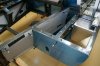
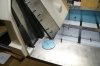
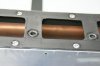
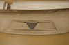
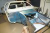
The tank was built by Tornado. If I understand the inside of the tank correctly, the back 10" is a compartment with foam in it and with some sort of baffle. in the middle of that compartment are the suction and return lines. The suction is on the bottom and has a line going to the bottom of the tank. The top return line is directly above the suction line so it dumps into the same compartment as the suction. In the photo below, the fittings are covered by tape.
The fuel gauge sender is just in front of and on the other side of that compartment (it is about even with the rear bulkhead) so I don't anticipate problems with the readings. See photo below.
The tees are large in order to have enough volume to get the fluid velocities low before they go somewhere else. I suspect it probably would have worked with regular tees, but I think this is safer.
The normal custom in hydraulics is to make the suction (low pressure) lines larger than the pressure lines to avoid cavitation. I wish that my suction lines were -8 (at least) for reasons of avoiding cavitation and to allow faster balance between tanks. That is my recommendation and perhaps they will be that way in the future, especially for fuel injection applications.
-Bob Woods
The fuel pump is a Bosch 044. When were your tanks built? I hope Tornado has addressed that problem now, but mine sounds like yours. Perhaps Andy will jump in here.
Bill,
The tank was built by Tornado. If I understand the inside of the tank correctly, the back 10" is a compartment with foam in it and with some sort of baffle. in the middle of that compartment are the suction and return lines. The suction is on the bottom and has a line going to the bottom of the tank. The top return line is directly above the suction line so it dumps into the same compartment as the suction. In the photo below, the fittings are covered by tape.
The fuel gauge sender is just in front of and on the other side of that compartment (it is about even with the rear bulkhead) so I don't anticipate problems with the readings. See photo below.
The tees are large in order to have enough volume to get the fluid velocities low before they go somewhere else. I suspect it probably would have worked with regular tees, but I think this is safer.
The normal custom in hydraulics is to make the suction (low pressure) lines larger than the pressure lines to avoid cavitation. I wish that my suction lines were -8 (at least) for reasons of avoiding cavitation and to allow faster balance between tanks. That is my recommendation and perhaps they will be that way in the future, especially for fuel injection applications.
-Bob Woods
Attachments
Last edited:
Tim Kay
Lifetime Supporter
Bob, with my Tornado one has to keep in mind my chassis is 20 years old and many parts have been replaced with new parts from Tornado and some have been redesigned and fitted "in house". Gas tanks are of the later, built in my shop. The original tanks, which may or may not be Tornado (not knowing where the original owner purchased the tanks), had no baffles but did have foam.
Tim
Tim
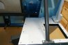
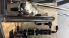
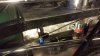
Here are some photos of what I ended up doing.
Our tanks are very similar. Mine too are foam filled (you will want to create an access panel to replace the foam with as this has to be done regularly given our oxygenated gas) and I removed the 6AN and replaced it with a larger size (can't recall off hand...I thought it ended up being larger than an 8AN but I'd have to look). I strongly suggest you do this too and almost feel it a requirement if you aren't using a swirl pot given the engine I recall you planning.
I have an 8AN line that runs between the two tanks toward the rear and a one way low pressure valve that keeps fuel from flowing back to the other side. I run a swirl pot as you can see in the photos. I hate to think about how much all this cost me in time and money, but I think it will be fairly bulletproof and isn't as complicated (and thus prone to breaking a given component) as a twin pump system with those Pollack valves.
The hole you see in the low pressure side photo is where the tie line between the two tanks comes in. Ignore the brake line (it hadn't been fastened into place when this was taken).
Attachments
It is time for an update.
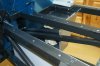
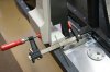
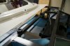
Roof Section - I have installed the rear mounts of the roof section. The right side rear mount had quite a twist to it (see first illustration below). The way I mounted it was to first drill the rear hole in the proper position, put a bolt in it, and then use a clamp to rotate the front part of the footing. I wanted the two bolts to have a large separation to hold the torque of the twist. Since I couldn't drill the correct size hole for the bolt directly, I used a very long small diameter drill to make a pilot hole and then took it apart and drilled both holes the correct size. It still has a little twist to it, I should have over compensated knowing there would be some slop. The left side didn't have as much of a twist.
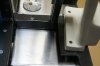
Side Sill Moldings - With the roof section located in the rear, I could put the side moldings on and trim to fit around the removable sections in the rear. It is amazing how many times you have to make small adjustments in fitting everything... They are now finalized except for final mounting. I have a strip of aluminum to cover the junction of the side moldings and the carpet. The trim will be removable.
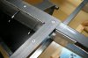
Gaskets for Rivet Nuts - I have several panels that will be removable and hence use Rivet Nuts to hold them in place. The thickness of the head of the Rivet Nut is 0.049". If I didn't do anything, there would be a gap between the two pieces. I found a sheet of rubber (used as a pond liner) that was 0.049" thick. I cut gaskets to go under everything that will be mounted with Rivet Nuts. Not only does it seal the gap between the top of the Rivet Nut and the frame, but it seems to provide substantial noise reduction.
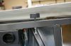
Dash Supports in the Front - The front part of the dash would droop down and not meet up with the front roof section. I couldn't find anywhere in the instruction manual on how to support the front of the dash. I would like to have the dash removable, so I came up with this technique. I found some rubber bumpers that had a 1/4" hole in the middle. I tapped a 1/4-20 hole in three places on the small tube going across the frame (I had to grind off about 1/4" of the shank above the last thread on the tap so it would go through both the top and bottom of the 1" rail). I then placed long bolts through the frame to be able to adjust the height of the rubber bumper. For the center bumper I had to place an aluminum plate over the triangular gap on the bottom side of the demister for the bumper to touch. I can now adjust the height of the bumpers to get the dash to touch the roof section. I can also remove the dash, but I will have to lift the front of the roof section by about 1/4" to clear the rib in the roof. That is ok since I plan to bolt and Rivet Nut the front of the roof down instead of using rivets.
Dash - Darrin started a thread on the dash about the same time I started working on my dash. There are some very interesting comments on that thread (Exterior, Interior, AC, & Trim). In particular, Clayton has a thermal vacuum formed vinyl dash that is stunning. I was going to cover the top part of the dash with leather and paint the rest, but I am now hunting for someone that can do the vacuum formed vinyl in the USA. So far I have found "Just Dashes" in California and "Al Knoch" in El Paso. I'm still looking... I have done the final preps on my dash and it is ready to go for vinyl or leather.
Current Status - Here are some views of my car to date. The next on the list is to mount the rear and front sections and then the doors. The doors don't look easy since there will be so much trimming.
-Bob Woods
Roof Section - I have installed the rear mounts of the roof section. The right side rear mount had quite a twist to it (see first illustration below). The way I mounted it was to first drill the rear hole in the proper position, put a bolt in it, and then use a clamp to rotate the front part of the footing. I wanted the two bolts to have a large separation to hold the torque of the twist. Since I couldn't drill the correct size hole for the bolt directly, I used a very long small diameter drill to make a pilot hole and then took it apart and drilled both holes the correct size. It still has a little twist to it, I should have over compensated knowing there would be some slop. The left side didn't have as much of a twist.
Side Sill Moldings - With the roof section located in the rear, I could put the side moldings on and trim to fit around the removable sections in the rear. It is amazing how many times you have to make small adjustments in fitting everything... They are now finalized except for final mounting. I have a strip of aluminum to cover the junction of the side moldings and the carpet. The trim will be removable.
Gaskets for Rivet Nuts - I have several panels that will be removable and hence use Rivet Nuts to hold them in place. The thickness of the head of the Rivet Nut is 0.049". If I didn't do anything, there would be a gap between the two pieces. I found a sheet of rubber (used as a pond liner) that was 0.049" thick. I cut gaskets to go under everything that will be mounted with Rivet Nuts. Not only does it seal the gap between the top of the Rivet Nut and the frame, but it seems to provide substantial noise reduction.
Dash Supports in the Front - The front part of the dash would droop down and not meet up with the front roof section. I couldn't find anywhere in the instruction manual on how to support the front of the dash. I would like to have the dash removable, so I came up with this technique. I found some rubber bumpers that had a 1/4" hole in the middle. I tapped a 1/4-20 hole in three places on the small tube going across the frame (I had to grind off about 1/4" of the shank above the last thread on the tap so it would go through both the top and bottom of the 1" rail). I then placed long bolts through the frame to be able to adjust the height of the rubber bumper. For the center bumper I had to place an aluminum plate over the triangular gap on the bottom side of the demister for the bumper to touch. I can now adjust the height of the bumpers to get the dash to touch the roof section. I can also remove the dash, but I will have to lift the front of the roof section by about 1/4" to clear the rib in the roof. That is ok since I plan to bolt and Rivet Nut the front of the roof down instead of using rivets.
Dash - Darrin started a thread on the dash about the same time I started working on my dash. There are some very interesting comments on that thread (Exterior, Interior, AC, & Trim). In particular, Clayton has a thermal vacuum formed vinyl dash that is stunning. I was going to cover the top part of the dash with leather and paint the rest, but I am now hunting for someone that can do the vacuum formed vinyl in the USA. So far I have found "Just Dashes" in California and "Al Knoch" in El Paso. I'm still looking... I have done the final preps on my dash and it is ready to go for vinyl or leather.
Current Status - Here are some views of my car to date. The next on the list is to mount the rear and front sections and then the doors. The doors don't look easy since there will be so much trimming.
-Bob Woods
Attachments
-
 rear and front holes drilled showing twist.jpg101 KB · Views: 1,142
 -
 small drill to mark location of front bolt.jpg118 KB · Views: 1,281
 -
 rubber gasket left rear sill cover.jpg112.8 KB · Views: 1,102
 -
 gasket on tunnel.jpg109.7 KB · Views: 1,093
 -
 dashboard bumper.jpg102.4 KB · Views: 1,090
 -
 dash supports top.jpg106.9 KB · Views: 1,198
 -
 dash supports bottom.jpg97.2 KB · Views: 1,126
 -
 middle support.jpg94 KB · Views: 1,046
 -
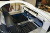 cockpit view.jpg147.3 KB · Views: 1,410
 -
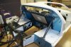 rear view.jpg168.5 KB · Views: 1,460
 -
 front view.jpg156.8 KB · Views: 1,363
Hi Bob
Really tidy work on your GT40...
Thanks for the update
Cheers Craig Young
Really tidy work on your GT40...
Thanks for the update
Cheers Craig Young
Similar threads
- Replies
- 14
- Views
- 1K
- Replies
- 42
- Views
- 4K