AK SPORTS CAR GT40

Not a lot has happend since last post...
but
Father Christmas has made an early stop...
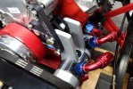
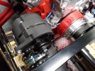
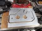
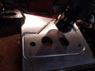
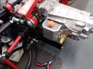
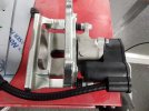
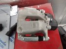
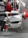
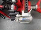
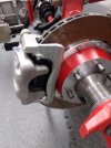
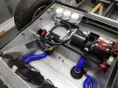
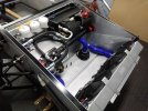
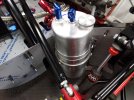
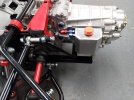
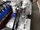
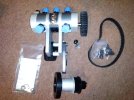
I have now decided to go with a dry sump system and taken delivery of an AVIAID geared pump and crank fittings for belt drive.
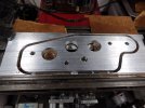
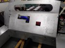
This means of course that have to take sump off, add some scavange connections ( -12) to the side of the sump. remove the internal oil pump and suction pipe. Block off the oil outlet from the pump.
I intend to run the pressure side after going thru external oil filter into the threaded portion where the oil filter used to spin onto.
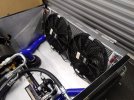
The scavange side will go thru oil cooler and return to dry tank.

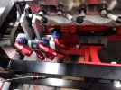
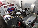
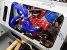
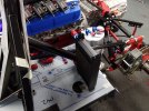
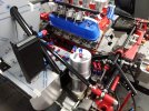
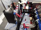
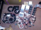
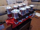
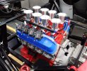
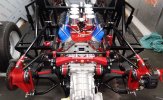
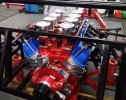
The other little present is an 8 stack Fuel injection system. Complete with a Holley Terminator ecu and coil near plug and accosiated wiring.
This was all supplied by a very good company in USA... Shakey B's Hot Rod Shop. They also supplied me with the fully finished bare block.
.
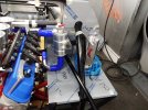
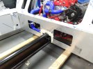
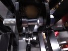
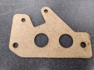
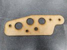
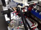
The pump still has to be fitted... the bracket it comes with assume its normal front engine with loads of front room !!!!
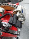
as we all know , space is very limited at front so going to have to modify bracketry to move pump back as far as possible.
Mounting it on the left side.
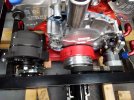
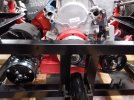
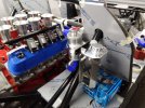
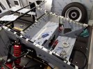
Have to squeeze in just one v belt pulley to drive the AIRCON pump ( this has 2 pulleys ) and then another v belt from AIRCON to alternator.
These will be mounted on the right hand side.. still got to design this lot and then fabricate.
A few pictures attached..
 

Attachments

  • IMG_2023-12-07-12-54-37-766.jpg
    IMG_2023-12-07-12-54-37-766.jpg
    389.3 KB · Views: 323
  • IMG_2023-12-07-13-10-28-928.jpg
    IMG_2023-12-07-13-10-28-928.jpg
    431 KB · Views: 277
  • IMG_2023-12-09-13-36-25-259.jpg
    IMG_2023-12-09-13-36-25-259.jpg
    420.4 KB · Views: 244
  • IMG_2023-12-09-13-36-38-993.jpg
    IMG_2023-12-09-13-36-38-993.jpg
    490.5 KB · Views: 248
  • IMG_2023-12-09-13-37-29-003.jpg
    IMG_2023-12-09-13-37-29-003.jpg
    438.6 KB · Views: 237
  • IMG_2023-12-07-12-28-08-751.jpg
    IMG_2023-12-07-12-28-08-751.jpg
    401.8 KB · Views: 260
I have changed my mind re water pump.
It did bulge way too far into cabin and comprimised my pulley arrangement.
I have now managed to fit the dry sump pump using the supplied brackets.
But had to move it quite a lot rearwards to stop it fouling the bulkhead !
I was going to use a take off adaptor for the oil feed but it got in the way of the oil pump.
so i have had to feed directly into the engine using an adaptor.
The 'nipple' sticking out that the filter screws onto was removed and the thread into the block was 1 1/16" -12
so i purchased a -12 to -12 adaptor. machined off the taper of one end so i had 12 mm of thread left.
this was then loctited / and silicone into the block.
Obviously , when i take engine out for paneling I will remove the existing internal oil pump, and block off its output.
This allowed me to screw on a -12 90 degree fitting and made room for the oil pump...nearly....
I had to machine / grind a bit off the rear of the pump to allow the pump to swing to tension the drive belt.
I turned up a drive pulley with 2 'A' form groves to match the air con pump and alternator.
I had to recess this so it fitted over the crank / pump drive adaptor that bolts onto the crank.
It is bloody tight in here up to the bulkhead..
I am going to machine up a couple of bolt on water intakes for the left and right input to the engine
I'm making these 1" dia.
I will then 'T' these into a 1.5" hose and run to the front of the car where I will fit a Craig water pump.
Swirl pot will be fitted to take water feed from after thermostat and then feed forward to other side of radiator. this will be pressure so will have rad cap. attached to this will be the blow off / top up / syphon container.
At the rear of the intake manifold there will be a bleed pipe to the swirl pot and also a bleed from the front radiator to the swirl pot. ( there are in fact 2 bleeds on rad so will 'T' these so only run one pipe back
I want a heater so I am running a 1/2" hose from the small pipe to the side of the thermostat cover ( direct connection to inlet manifold before thermostat ) forwards to the heater matrix vis a Focus Diverter control. and then run a return pipe to the 3/8" NPT hole that's in the thermostat housing just before the 1.5" outlet ( this is after the thermostat ).
The FOCAS diverter valve is solenoid driven and either allows water to flow thru heater matrix or bypasses it and just returns the water.
This allows a constant flow of water ( by pass hose ) around the engine.
I would guess that when the thermostat opens then the heater will cool down as water will take least resistance and flow thru the main rad.
but its better than nothing !!!
The other side of the engine is a head scratcher at the moment...
The air con pump will be hard fitted to engine and not movable.
The alternator will be on a swinging bracket to tension the drive belt.
The belt will go round the forward pulley slot on engine , and then round forward pulley on A/C unit and then up around the alternator and then back down to crank pulley.
There are a lack of bolt pickups on this side so may have to make up brackets that come off the head ( 3 positions ) and then something coming off the engine mount bolts ...
The pulley on the crank that drives the Oil pump is rather close to the front bulkhead chassis so when i take engine out i am going to cut out some of the tubes and move them to make a recess for the pulley.
Also going to make up a couple of for / aft rose joint rods to connect engine to chassis to stop any forward / rearward movement.
Did this on race car. it did not seem to add any engine vibration to cockpit.
I have added some pictures to show how far I have got.
 

Attachments

  • IMG_2023-12-23-12-43-07-065.jpg
    IMG_2023-12-23-12-43-07-065.jpg
    367.6 KB · Views: 169
  • IMG_2023-12-23-12-43-13-221.jpg
    IMG_2023-12-23-12-43-13-221.jpg
    359.3 KB · Views: 164
  • IMG_2023-12-23-12-43-28-972.jpg
    IMG_2023-12-23-12-43-28-972.jpg
    351.4 KB · Views: 159
  • IMG_2023-12-23-12-43-44-473.jpg
    IMG_2023-12-23-12-43-44-473.jpg
    359.3 KB · Views: 163
WINDSCREEN INFO AS REQUESTED.
PICTURES FOLLOW
 

Attachments

  • IMG_2024-01-26-23-09-56-757.jpg
    IMG_2024-01-26-23-09-56-757.jpg
    311.5 KB · Views: 100
  • IMG_2024-01-26-23-10-24-300.jpg
    IMG_2024-01-26-23-10-24-300.jpg
    314.8 KB · Views: 101
  • IMG_2024-01-26-23-11-07-886.jpg
    IMG_2024-01-26-23-11-07-886.jpg
    272.1 KB · Views: 98
  • IMG_2024-01-26-23-11-37-751.jpg
    IMG_2024-01-26-23-11-37-751.jpg
    177.1 KB · Views: 96
  • IMG_2024-01-26-23-12-23-551.jpg
    IMG_2024-01-26-23-12-23-551.jpg
    240.9 KB · Views: 98
  • IMG_2024-01-26-23-13-15-092.jpg
    IMG_2024-01-26-23-13-15-092.jpg
    213.5 KB · Views: 128
Moved on a bit since last post.
trial fit of all ally panels.
quite a few cut and shut needed on the panels....
have started to drill for panels at front..
gone for a 55 mm spacing...looks about right
made the access panel cutout in rear bulkhead a lot bigger for easier access and also added 2 cutouts in the lower rear panel to make access to alt and A.C a lot easier.
sorted out the alternator and a/c pump fittings with new brackets.
dry sump tank now arrived so have decided where to put.
also where to put remote oil filter.
The original panels from AK for the rear are angled to give impression of Monoque .
I did not like the fit of these and also would have meant putting dry sump tank behind rear axle ...not a good position.
so am going to make up a couple of new panels and square it off. and this then makes room for tank
water swirl installed.
have put in a overflow / syphon tank..
also have to put in oil catch tank / breather from dry sump tank..prob bolt on to gearbox as getting tight for space on left side.
as i want to put fuel system on this side.
need to weld on some return lines to swirl.
one from radiator and one from rear of intake manifold.
lots of pictures attached. I hope they are self explanatary.
 

Attachments

  • ac pump bracket.jpg
    ac pump bracket.jpg
    520.9 KB · Views: 89
  • all panels fitted. taped in .jpg
    all panels fitted. taped in .jpg
    471.9 KB · Views: 91
  • alt bracket.jpg
    alt bracket.jpg
    446.8 KB · Views: 93
  • brackets and hoses all in.jpg
    brackets and hoses all in.jpg
    409.4 KB · Views: 96
  • coolant swirl and ov erflow . cyphon..jpg
    coolant swirl and ov erflow . cyphon..jpg
    542.7 KB · Views: 92
  • coolant swirl.jpg
    coolant swirl.jpg
    432.9 KB · Views: 90
  • cooler and dry sump.jpg
    cooler and dry sump.jpg
    481.9 KB · Views: 93
  • extra panel holes for easy access.jpg
    extra panel holes for easy access.jpg
    349.5 KB · Views: 92
  • front panel drilling.jpg
    front panel drilling.jpg
    478.9 KB · Views: 96
  • milling out A.C pump bracket.jpg
    milling out A.C pump bracket.jpg
    307.8 KB · Views: 99
some more pictures
 

Attachments

  • oil  side. dry sump cooler filter.jpg
    oil side. dry sump cooler filter.jpg
    459.3 KB · Views: 100
  • position of oil catch tank.jpg
    position of oil catch tank.jpg
    400.4 KB · Views: 94
  • rear arm radius on spacers.jpg
    rear arm radius on spacers.jpg
    217.4 KB · Views: 99
  • started to drill for panels.jpg
    started to drill for panels.jpg
    446.3 KB · Views: 93
  • wood mock up ac bracket.jpg
    wood mock up ac bracket.jpg
    396.1 KB · Views: 94
  • wood mock up alt bracket.jpg
    wood mock up alt bracket.jpg
    562.5 KB · Views: 99
Well here we are again with a few more pictures showing progression.
I have decided to take the electric caliper handbrake route. !!! pictures attached.
Was sort of forced into this route due to having dry sump and engine very hard up against Bulkhead.
major work needed on these calipers to clear the wheel and disc and have to make up holding brackets.
Have to do some electronic design and build to control these correctly.

Rad, air con, pump and hyd resevoirs fitted. I decided that I would put the air con and heater in the front section.
Yes, i appreciate it makes access to steer rack impossible.
But i have split the panel alongside the air con so can get at one side.
And if shove comes to push and i need access then I can just remove air con.!!

Air con pipes run in. decided that i would use unions and bulkhead fittings rather than bend and twist some very heavy stiff pipe !
also makes for a much neater appearance . I had purchased the crimping tool from ebay..seems to work ok but the proof will be when I test pressure and test vacum on it.

Craig davies ewp 80 fitted. This pulls from the bottom of the swirl pot, pushes thru rad and into the 2 inputs on the block, this then exits thru the thermostat and into the top of the swirl pot.
When the stat is closed ( cold ) the flow is sent around the heater matrix and back. I am also putting in a small heater water pump as I suspect that when the thermostat opens i will get no flow thru the heater.

Air/water bleeds still to be added from rad top to top of swirl pot.
Air water bleed added from rear of manifold to top of swirl pot.

Pedal box just placed in position..

Fuel will be held in both tanks but the r/h will be reserve. This can be pumped into the l/h tank when required by the pump on the rear r/h side.
The fuel return fitting on the r/h tank has been blanked off.

an extra fuel union has been added to the l/h tank to allow pumped fuel from the r/h tank.

Fuel feed from base of l/h tank thru filter then to pump then to fuel swirl
Top of swirl will go back to tank using existing return fitting on tank.

Bottom of fuel swirl will go through filter to HP pump then to filter then to fuel rail, then return thru pressure regulator to fuel swirl pot
I have not yet worked out the heater pipe runs.
Dry sump tank fitted and oil catch tank.
I have reworked the rear alloy panels different to AK to allow the dry sump tank to fit.

Not yet made up brackets to support the oil cooler. I have carried out a 'trial' fit of spider and rear to make sure no clearance issues with cooler.
all looks good but will do final fit of cooler after body fit so that it is in intake duct area

When the engine is taken out i have to modify the front of the sump on the oil pump side as the scavenge unions fitted to the pump foul it.
also have to weld on the sump scavenge unions and internal filter gauze.

So thats about it so far.
 

Attachments

  • IMG_2024-03-27-13-41-33-015.jpg
    IMG_2024-03-27-13-41-33-015.jpg
    424.1 KB · Views: 46
  • IMG_2024-03-27-13-41-48-541.jpg
    IMG_2024-03-27-13-41-48-541.jpg
    349.3 KB · Views: 47
  • IMG_2024-03-27-13-41-59-361.jpg
    IMG_2024-03-27-13-41-59-361.jpg
    184 KB · Views: 48
  • IMG_2024-03-27-13-42-05-464.jpg
    IMG_2024-03-27-13-42-05-464.jpg
    375.3 KB · Views: 49
  • IMG_2024-03-27-13-42-09-702.jpg
    IMG_2024-03-27-13-42-09-702.jpg
    202.9 KB · Views: 55
  • IMG_2024-03-27-13-42-15-801.jpg
    IMG_2024-03-27-13-42-15-801.jpg
    186.6 KB · Views: 55
  • FRONT PANEL VIEW.jpg
    FRONT PANEL VIEW.jpg
    443.2 KB · Views: 56
  • FRONT PANELS WITH AIR CON AND RAD FITTED.jpg
    FRONT PANELS WITH AIR CON AND RAD FITTED.jpg
    382.8 KB · Views: 56
  • FRONT VIEW OF RAD AND FANS.jpg
    FRONT VIEW OF RAD AND FANS.jpg
    395.7 KB · Views: 53
  • GENERAL VIEW OF FRONT AND COCKPIT PANELS.jpg
    GENERAL VIEW OF FRONT AND COCKPIT PANELS.jpg
    390.6 KB · Views: 55
some more pictures
 

Attachments

  • LEFT REAR FUEL SYSTEM.jpg
    LEFT REAR FUEL SYSTEM.jpg
    431.1 KB · Views: 56
  • LEFT REAR SHOWING POSITION OF ALL THE FUEL AND OILY BITS.jpg
    LEFT REAR SHOWING POSITION OF ALL THE FUEL AND OILY BITS.jpg
    381.4 KB · Views: 56
  • PANEL 80 GRIT AND THEN 320 GRIT THEN SPRAYED. NYALIC.jpg
    PANEL 80 GRIT AND THEN 320 GRIT THEN SPRAYED. NYALIC.jpg
    334.7 KB · Views: 55
  • REAR BULKHEAD PANELS.jpg
    REAR BULKHEAD PANELS.jpg
    305.2 KB · Views: 56
  • REAR LEFT SHOWING DRY SUMP OIUL TANK AND NEW PANELS.jpg
    REAR LEFT SHOWING DRY SUMP OIUL TANK AND NEW PANELS.jpg
    456.8 KB · Views: 55
  • REAR LEFT SHOWING OIL MCATCH TANK.jpg
    REAR LEFT SHOWING OIL MCATCH TANK.jpg
    390.3 KB · Views: 53
  • REAR RIGHT TRANSFER FUEL PUMP AND WATER SWIRL.jpg
    REAR RIGHT TRANSFER FUEL PUMP AND WATER SWIRL.jpg
    427.1 KB · Views: 54
Keep up the good work Jerry!

You are putting in some very meticulous work and it is looking great.

I hope to soon start paneling up my AK40 soon.

I have a few more modifications to the frame to go and then the paneling can begin.
 
Thanks Douglas,
Your build is coming along nicely... are you making panels from scratch or a few 'off the shelf' from AK.
I like the picture of the 'shrink wrapped' body ......
Jerry
 
Craig davies ewp 80 fitted. This pulls from the bottom of the swirl pot, pushes thru rad and into the 2 inputs on the block, this then exits thru the thermostat and into the top of the swirl pot.
Thought the EWP needs to be installed after the lower rad hose as its designed to pull, not to push.
 

Morten

Mortified GT
Supporter
Do you have any bleed hose from top of manifold or thermostat housing to headertank in addition to the hose from the radiator?
 
Thanks Douglas,
Your build is coming along nicely... are you making panels from scratch or a few 'off the shelf' from AK.
I like the picture of the 'shrink wrapped' body ......
Jerry
Jerry,

I have the panel kit, the majority will work as is, others will be adjusted or made new.
 
Back
Top