Weber 48 IDA - Show me your linkages

Randy V

Moderator-Admin
Staff member
Admin
Lifetime Supporter
Hi Guys,

I've done the search thing and am at a loss for what I need.

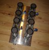
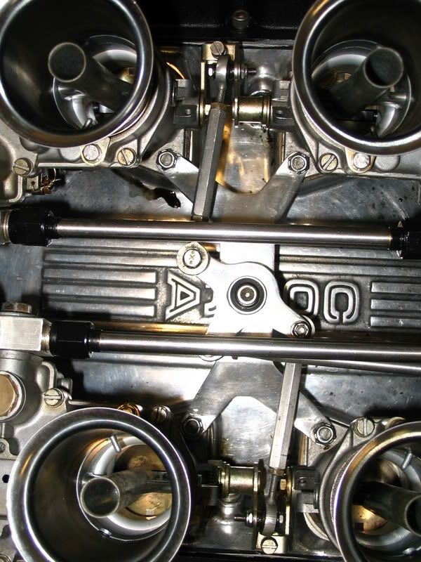
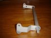
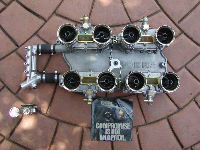
I'd like to modify the linkage on my setup that I just bought from Jack to use center linkage to both rows of carbs. It did have a single center link to one row and the opposite row was linked via the end carbs.
I'm not that concerned about shaft flex/twist because these are the new style carbs with the hardened steel shafts.
I'd like to see what you've done. Please consider posting some detail pictures to help me and others that may follow..

IMG_8967.jpg
 

Doc Watson

Lifetime Supporter
I'm going for the original look with a central shaft (photo) which has 2 'T' plates brazed onto it. This part is attached to the base of a turkey pan with 2 pillar bearings. Each throttle is connected to the hole at the top of the 'T' plates with adjustable linkages. The throttle cable attaches to the (far end in the photo) 'T' plate, in the lower central hole.

The 'T' plate at the rear of the engine is the one closest in the photo and has a step bent into it, this allows the turkey pan to be shorter at the rear of the engine.

I'm waiting for the pillar bearings to arrive so I can set up the linkage system.

If you go to the website below you will see a photo of the system in figure 15.

Ford GT40 Restoration - The Motivation

Although it shows 2 shafts and 'T' plates, and 1 set of linkages, you can see the pillar bearings.

This setup also makes the throttle cable come off the engine in the middle of the IDA's.

Andy
 

Attachments

  • throttle link 001.jpg
    throttle link 001.jpg
    26.2 KB · Views: 1,044
Doc-
I've been working on the same sort of linkage for the same reasons--originality and avoiding shaft twist. Over here though, we call this kind of bearing a "pillow" block, if that's what you have in mind.


Two countries, separated by a common language...:)
 

Attachments

  • pillow block bearing.jpg
    pillow block bearing.jpg
    21.1 KB · Views: 889

Randy V

Moderator-Admin
Staff member
Admin
Lifetime Supporter
Great pictures guys and a HUGE help - please keep them coming!

Dean & Rick - Do you have a close-up of the linkage as it ties to the center between the carbs in each row? A side view would be great!

Thanks fellas...
 
Doc-
Did you fabricate the bearing blocks and arms yourself or are they available commercially? As I remember you were working on a turkey pan--how's that going, and will you mount the linkage assembly directly to it?
Thanks,
John

I think I like pillar block better than pillow block. Sounds more industrial somehow.
 

Doc Watson

Lifetime Supporter
The arm is an original and the blocks are being made from original drawings. The base of the turkey pan is nearly complete. All bolt holes and inlet holes have been produced. The inlet holes were matched by using a small file to ensure an exact match with the inlet manifold. The distributor end still needs to be cut correctly and am waiting (still!!!) for the engine before cutting it to correct size. The sides of the turkey pan cannot be produced correctly without the chassis and rear clip in position which wont be with me until later this year. There is a few pictures in my engine build thread. The pillow bearings are attached to the base of the turkey pan with bolts, knowing this is the case I made the base with 3mm aluminium plate to stop any flexing.

http://www.gt40s.com/forum/gt40-build-logs/19346-gt40-engine-build-mirage-chassis.html

Andy
 

Attachments

  • coldboxplate01.jpg
    coldboxplate01.jpg
    47.4 KB · Views: 982
You should not put information on the forum if you can not verify if it is correct. I have the original drawings, and unfortunately you have made quite a few errors. First off, I hope no one else has to hold their car together with the carburetor box as you may have sugggested. Secondly, there are three different versions, a Cobra version, an E & F version, and one for the Gurney Weslake heads. The spacing on the Cobra and the E&F version are different in both width and length. The Gurney Weslake version is an entirely different animal. Thirdly, the original print calls for the base plate to be made from 10 S.W.G. or .128" Dural. Get your facts right.
 

Doc Watson

Lifetime Supporter
First off - whats wrong with my carb box?
Second - did I say that mine was the only type????
thirdly - I gave my reasons for the 3mm base plate and didnt say that was what the originals use, and oh my god im real sorry man for posting MY throttle base plate which happens to be 0.2512 mm undersize.

I did say that I have an original throttle lever, any problems with that!!!!

Wind your neck in.
 
Doc-
With the T configuration of the lever, the geometry of the linking arms to the carbs is going to be a little different for the left and right banks; do you forsee any problem getting the throws the same?
 

Doc Watson

Lifetime Supporter
John,

I agree the geometry needs to be looked at with a view to the placement (and height) of the throttle shaft in relation to the webers (for my manifold which is a modified cobra manifold all of the webers face the same way). I'm going to look at this this weekend and will post results. There is also the factor of the butterfly valves opening in different directions for my set-up which has been discussed here....

http://www.gt40s.com/forum/gt40-tec...right-way.html?highlight=webers+the+right+way

Andy
 
By the way, there is nothing wrong with your carb box as long as you use it on a lawnmower or whatever.
 

Doc Watson

Lifetime Supporter
Oh you mean this lawnmower....... yes I understand now......
 

Attachments

  • chassis02.jpg
    chassis02.jpg
    27.1 KB · Views: 780
Last edited:
Back
Top