Diy 8 stack

8 stack

I will post up over a period as I cant give this time in one hit, the project is progressing so I will start now and keep adding.

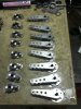
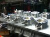
I decided to make an 8 stack for my 96 cobra modular engine.

I didn’t want to buy one because that goes against the grain.

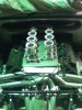
The engine I have has a split port design, in one port it has a second set of butterflies this has been programmed to come on at 4.500rpm, the factory turns it on at about 3.500rpm.

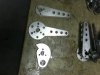
The job of fabricating the lower section was deemed as to time consuming for the minor benefits if any that I may have been able to get.

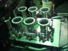
The injectors are in the secondary throttle plate and this was also a factor as I wanted to retain their location as well as the secondary butterflies.

I gave up looking for a factory manifold as it seemed impossible here in Aust.
But one came up on fleebay about a month ago so I’m into it.

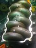
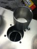
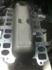
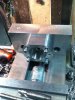
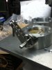
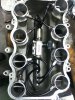
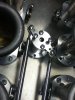
The first pic is the factory manifold with the top hat and throttle body taken off, it exposés the runners inside the plenum.

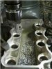
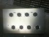
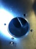
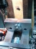
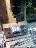
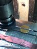
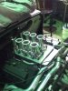
I attacked it with an air hacksaw to get the majority out then set it up in the mill and machined out the remainder.
 

Attachments

  • IMG_0028.jpg
    IMG_0028.jpg
    271.1 KB · Views: 356
  • IMG_0035.jpg
    IMG_0035.jpg
    252.2 KB · Views: 319
  • intake manifold.jpg
    intake manifold.jpg
    12.2 KB · Views: 407
After machining out the remainder I then had the measurements for the second stage.

I used 10mm alloy plate as I don’t want the t/bodies to move around .

Drilled and tapped holes for the throttle bodies to mount to.

I used the original ford gasket as it very good.

I counterbored the holes for the bolts that mount the plate to the manifold base as they will foul the t/bodies.

I was very nervous at the last hole because their is really no room for error when it all comes together
 

Attachments

  • IMG_0023.JPG
    IMG_0023.JPG
    211 KB · Views: 296
Last edited:
I worked out some port area ratios, the valve size is 37mm each ,that makes it about 52mm if it was 1 valve.

The entry in the port at my counter bore in the factory manifold is 45mm, that makes it about 86% STD so I’m not playing with that.

When we use the open port it has a ratio of 72% that is why it has good pull down low.
When the secondary port opens and the 2 are in use it is 97% which is way to big but it seems to work for it.
The secondary b/flies are either on or of but I am going to look at working something out at a later date to step it as required to get more out of it.

Tapered tube to meet port to plate,the tubes will be o'ringed but I have not had a chance yet.

The 3rd pic is of the ports on the exit of the manifold
 

Attachments

  • IMG_0067.jpg
    IMG_0067.jpg
    201.6 KB · Views: 264
  • IMG_0069.jpg
    IMG_0069.jpg
    195 KB · Views: 299
  • IMG_0031.jpg
    IMG_0031.jpg
    205 KB · Views: 294
Last edited:
I decided on 48mm TB due to their location in the port and. the length is going to governed by the back window unfortunately ,I am chasing about 15 " from the valve seat but I may end up shorter ,thats life.

The ID of the trumpet is 55 at the entry which is just over the valve size.

I already had a body design in my head so that was straight forward.

The best thing I made was this jig.
I take the jaw out of the vice and bolt it in then datum of and plough through the process's.

It does seem to go on forever at stages but you just keep going.
 

Attachments

  • IMG_0052.jpg
    IMG_0052.jpg
    286.5 KB · Views: 294
  • IMG_0053.jpg
    IMG_0053.jpg
    306.8 KB · Views: 287
  • IMG_0055.jpg
    IMG_0055.jpg
    310.2 KB · Views: 262
Last edited:
Going for 8TB was my option due to bore spacings and also I want to open the BF to favour the open port not the closed port ,I cant do that with a webber style setup.

The shafts I did buy and cut them in half.
The shaft were a pain in the arse,they stress relieve after they machined the slot I think
.The amount of dicking around to get them right was painful.
I machined flats to suit using the BF as a datum plane.

The linkages I did on the cad to get a even sweep from close to open, I put flats on the shaft section to get indexing and a positive lock on the shaft.

Machined ss spacers with grubs and put them together on a jig.
Made a posts for the idle screw to mount into it also doubles as a throttle stop
 

Attachments

  • IMG_0060.jpg
    IMG_0060.jpg
    301.4 KB · Views: 258
  • IMG_0062.jpg
    IMG_0062.jpg
    217.1 KB · Views: 230
  • IMG_0061.jpg
    IMG_0061.jpg
    275.3 KB · Views: 234
  • IMG_0063.jpg
    IMG_0063.jpg
    228.2 KB · Views: 234
Have all bar one finished at this point ,short a bearing.

Made delrin sleeves for the coil springs to live on.

Starting to get to the dummy up stage.

Have to go I will put more up later

Jim
 

Attachments

  • IMG_0059.jpg
    IMG_0059.jpg
    206.1 KB · Views: 379
  • IMG_0065.JPG
    IMG_0065.JPG
    255.3 KB · Views: 375
  • IMG_0070.jpg
    IMG_0070.jpg
    232 KB · Views: 427
Jim, thats just fantastic. The level of engineering excellence on this forum never fails to amaze me.

It also makes me feel somewhat inadequate. :(
 

Terry Oxandale

Skinny Man
Great work! I admire the DIY approach to anything, and you've certainly done that here.

Question: Is the sleeve in each port held in place by pinching it between the OEM intake manifold piece, and the TB, when the TB is mounted?
 
Great work! I admire the DIY approach to anything, and you've certainly done that here.

Question: Is the sleeve in each port held in place by pinching it between the OEM intake manifold piece, and the TB, when the TB is mounted?

I have a few options Terry.

I will need to match port the tube to head and head to tube in some places so I will need to pin the tubes,I am thinking drilling between the tube and the top plate and installing a rolled pin,the pin will be left long so it can be removed,the extra length would pass into a hole drilled on the underside of the TB mounting face.

The o'rings will be 5mm down from the top and 5mm up from the bottom on the OD of the tube.
Had thought about crushing them but the TB are sensitive to a point and I didn't want to tempt fate.
I have not done anything about it yet as time often brings a better idea.

Jim
 
Great work! I admire the DIY approach to anything, and you've certainly done that here.

Question: Is the sleeve in each port held in place by pinching it between the OEM intake manifold piece, and the TB, when the TB is mounted?

Thanks gents for the kind words.

To answer Terrys question properly as I ran the experiment today with the fixing of the tubes.

The ports in the manifold only need a blend to the tubes ,so it wont matter the position
of the tube and will not require pinning.
I also machined the oring grooves and it is very snug so I am going with that.
 

Attachments

  • IMG_0071.jpg
    IMG_0071.jpg
    269 KB · Views: 306

Terry Oxandale

Skinny Man
Excellent. I wasn't sure if you would be o-ringing the base and top (squeezing the o-rings against the ends of the tubes), but the thin walls of the tubes may make this impractical.
 
Kevin

No I had them spun,he had the exit ID I wanted but not the entry, so he free handed the entrys .
$17 each you cant make them for that.

If you look at post #6 the front one I cleaned up with emery paper on the lathe,the rear ones you can see his free handing marks,Hes pretty good they are all the same.

Jim
 
More work done.

I want an idle control mainly for cold start, a/cond is not an issue the engine hardly see's it when turned on.

Each port is taped into and plumbed to a manifold I made and mounted in the floor of the old plenum that is now disused space.
Mounted an IAC motor on the manifold,I bored a hole in the back of the plenum to draw air in to feed it.

Oringed all the runner tubes top and bottom.
 

Attachments

  • IMG_0073.jpg
    IMG_0073.jpg
    293.5 KB · Views: 285
Big day with linkages ,I felt I had 2 choices 1 was a centre bellcrank a link going to a throttle shaft on either bank then the linkages on the outside ,I was concerned about loading 1 shaft with 4 TB springs so I went the 2nd option and that is a separate set of shafts and levers at the rear ,then joining via a short link.

On the bench everything seems fine,I wanted to stick the extra shafts at the front so you dont see them but it will interfere with the air box and filter assembly.

I hope by next week it will be running.

I will do the air box come filter then dyno.

Jim
 

Attachments

  • IMG_0079.jpg
    IMG_0079.jpg
    266.9 KB · Views: 259
  • IMG_0078.JPG
    IMG_0078.JPG
    264.6 KB · Views: 262
  • IMG_0081.jpg
    IMG_0081.jpg
    231.4 KB · Views: 253

Kevin Box

Supporter
Well done Jim

How did you get the TPS set up ???

Now all you've got to do is sync them
Did you do a before and after Dyno run ???


regards

Kevin B
 
Back
Top