Alternator & Starter Fuse Question

Joel K

Supporter
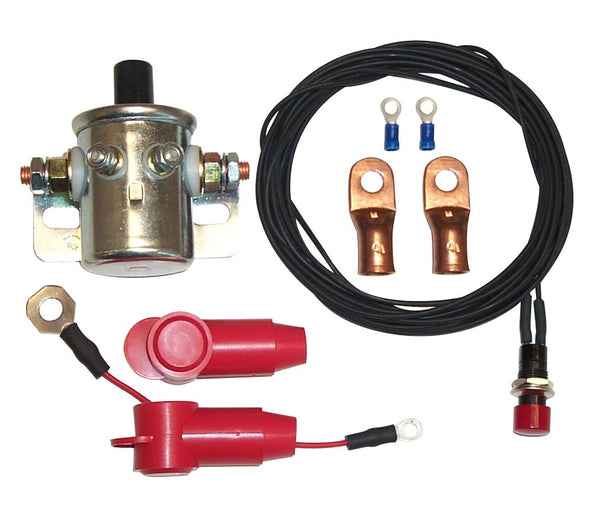
I am using this:


ECU has direct wire from battery for memory.

Steve,

How does this device cut the battery off, but keep the radio and EFI presets in place?
 
Joel,

Attached is a .pdf file of my primary wiring schematic showing how I wired my car. My starter and battery are very close so I ran a direct wire to the starter with no fuse or fusible link. I probably should have a fusible link but I have had issues in the past with them heating up being too close to a header (my own fault) and causing a high current draw "blowing" the fuse. I have a 100 amp breaker inline for all other battery connections and two separate power circuits for all battery connections. One constant on, one thru a Flaming River disconnect mounted in the dash that is basically my "key" for the car. Let me know if you have any questions.
 

Attachments

  • wiring1.pdf
    181.5 KB · Views: 90

Steven Lobel

Supporter
Steve,

How does this device cut the battery off, but keep the radio and EFI presets in place?
I have an LS7 with GM ECU. The ECU has a direct wire from the battery. This solenoid interrupts battery and alternator and shuts car down. What's a radio?
 

Joel K

Supporter
Joel,

Attached is a .pdf file of my primary wiring schematic showing how I wired my car. My starter and battery are very close so I ran a direct wire to the starter with no fuse or fusible link. I probably should have a fusible link but I have had issues in the past with them heating up being too close to a header (my own fault) and causing a high current draw "blowing" the fuse. I have a 100 amp breaker inline for all other battery connections and two separate power circuits for all battery connections. One constant on, one thru a Flaming River disconnect mounted in the dash that is basically my "key" for the car. Let me know if you have any questions.

This is great Kurt, thanks so much.

Did you just ground to chassis? Or did you run a few blocks, one in the front, rear, and passenger compartment like this…
9C060ADC-6003-4E07-9EA1-95852602E318.jpeg
 

Howard Jones

Supporter
Maybe have a look at this wire rating chart, It appears that some of the cable sizes are underrated compared to the protection ratings of the circuit breakers they are feeding. Particularly the grounds at the battery, the 2-Guage feed for the starter, and the early 2-gauge connections feeding the 150 amp CB and it's feed connections to the bus as well as 2-gauge feed cables to and from the 100 amp CB's.

It is common to exceed the total protection device values downstream and size the feed conductor (wire) by at least 150%. Why? because the CB is rated at less than 150 amps continuous duty. Then it will take some amount of time to trip at 150 amps. However, in a short circuit condition, the current rating of the CB may be exceeded by many times for a short period of time. Using an intentionally oversized conductor can prevent overheating of the cables should this type of fault occur.

A car battery can supply far more than 1000 amps in a short circuit fault and do so in less than 2-3 milisconds. If the CB cannot react that fast then the system conductors will experience this high current condition until it does.

It is also unusual to see CB's in series where the main feed CB sizing is less than the total downstream CB total protection value. Usual a total system main circuit breaker will equal the total of the separate downstream branch CB's.

What I would do is use the 150 amp CB to feed the starter power circuit and uprate its conductors to 2/0. Then uprate the ground conductor sizes to the same 2/0. You may find that in a long start, a multiple-try start, or a very hot engine the CB will trip. If this becomes an issue then upsizing the CB may be necessary and maybe even the conductor size if the cables get very hot.

Then feed the bus directly from the battery plus connection and keep this length of conductor as short as possible. The best case would be to place the bus right at the battery location and connect it with a short length of 2/0 feed conductor.

Neither the audio amp or the Holley ECU seam to have any protection on this diagram.

However if you meant to say 2/0 where you have indicated 2-guage then some of these others will be OK.

This is all my friendly offered opinion. And it was free.

Included is a paper on battery short circuit fault current capacity. Attention to figure 2 and keep in mind this data is for a 12 VDC 33AH AGM glass mat battery used in industrial backup systems and is of relatively moderate size and current capacity compared to automobile type AGM glass mat types. Many of them are 40 -100AH rated. Typically about 50-60AH rated. In any case, an automotive 12v battery can supply far more than a 1000A in a short circuit condition fault such as a starter armature shorted to ground internally.


Last edited:

Neil

Supporter
Maybe have a look at this wire rating chart, It appears that some of the cable sizes are underrated compared to the protection ratings of the circuit breakers they are feeding. Particularly the grounds at the battery, the 2-Guage feed for the starter, and the early 2-gauge connections feeding the 150 amp CB and it's feed connections to the bus as well as 2-gauge feed cables to and from the 100 amp CB's.

It is common to exceed the total protection device values downstream and size the feed conductor (wire) by at least 150%. Why? because the CB is rated at less than 150 amps continuous duty. Then it will take some amount of time to trip at 150 amps. However, in a short circuit condition, the current rating of the CB may be exceeded by many times for a short period of time. Using an intentionally oversized conductor can prevent overheating of the cables should this type of fault occur.

A car battery can supply far more than 1000 amps in a short circuit fault and do so in less than 2-3 milisconds. If the CB cannot react that fast then the system conductors will experience this high current condition until it does.

It is also unusual to see CB's in series where the main feed CB sizing is less than the total downstream CB total protection value. Usual a total system main circuit breaker will equal the total of the separate downstream branch CB's.

What I would do is use the 150 amp CB to feed the starter power circuit and uprate its conductors to 2/0. Then uprate the ground conductor sizes to the same 2/0. You may find that in a long start, a multiple-try start, or a very hot engine the CB will trip. If this becomes an issue then upsizing the CB may be necessary and maybe even the conductor size if the cables get very hot.

Then feed the bus directly from the battery plus connection and keep this length of conductor as short as possible. The best case would be to place the bus right at the battery location and connect it with a short length of 2/0 feed conductor.

Neither the audio amp or the Holley ECU seam to have any protection on this diagram.

However if you meant to say 2/0 where you have indicated 2-guage then some of these others will be OK.

This is all my friendly offered opinion. And it was free.

Included is a paper on battery short circuit fault current capacity. Attention to figure 2 and keep in mind this data is for a 12 VDC 33AH AGM glass mat battery used in industrial backup systems and is of relatively moderate size and current capacity compared to automobile type AGM glass mat types. Many of them are 40 -100AH rated. Typically about 50-60AH rated. In any case, an automotive 12v battery can supply far more than a 1000A in a short circuit condition fault such as a starter armature shorted to ground internally.


I used 2/0 "welding cable" for my battery-to-starter connection. Battery cable is very flexible and easy to route through a chassis.
 

Joel K

Supporter
Ok gang, looking for some more feedback. I came up with two potential designs for the main fuse layout. I reviewed Kurtiss and Kurt’s schematics and read through everyone’s comments. Appreciate your thoughts on either approach. Option 2 is simpler and cheaper, Option one may provide better isolation.

Based on battery location, I have very little room to run a fuse panel in the rear close to the battery. As Ken pointed out, the Zcase fuses are nice and compact So thinking of using those.

So I came up with these two designs:

Option 1) Separate ZCase fuses for the pdm and accessoy loads, starter, and alternator. Littlefuse makes starter specific type Zcase fuses starting at 300AMP up to 600AMPs

Option 2) This one is similar to Kurtiss‘s where the starter, alternator, and all loads run off a single 250Amp Mega fuse.

875076E3-5D36-4F79-AF6F-F3DB606576DC.jpeg
 

Ken Roberts

Supporter
I would go for option #1. You can later change/tailor the values of the fuses for the alternator or starter circuit. I think your fuse for the alternator is a bit high. I would try a 200amp fuse.

This style of fuse is fairly new and not readily available yet at some retail stores. I would suggest buying a couple extra in different values.
 
Last edited:

Joel K

Supporter
Just following up on this thread. I went with option #1. Purchased a fuse block which uses Marine Rated Battery fuses. It’s pretty compact and there are a lot of fuse sizes to choose from.

Made a bracket to mount this above the battery…
A39CA302-0F3E-4874-AC87-8EFBFAD621E4.jpeg


Installed on the chassis, the block comes with an acrylic cover…
C0C2AADA-4DF9-40EF-A078-7C1C0F03EA4C.jpeg


Now need to run some cables.
 
Back
Top