Build Diary - RCR Lola T70 Spider

Howard Jones

Supporter
Ron here's a couple of ideas. In the first picture you can see I did just about the same thing with my alternator except I move it inboard and lower one bolt hole on the head face. The belt tension adjustment is a simple L/H R/H piece of tubing with two rod ends. In the second I found a water pump pulley that has the center line of the belt in line with the bearing.
 

Attachments

  • HPIM0242.jpg
    HPIM0242.jpg
    186 KB · Views: 1,672
  • HPIM0241.jpg
    HPIM0241.jpg
    229.1 KB · Views: 1,688
Last edited:

Ron McCall

Supporter
Howard,
Where did you get te turnbuckle(adjuster)?

Ron ,
I had the same problem with my fuel pump except that someone had welded the inlet fitting to the housing and I couldn't get to the bolt under it to clock it differently.
I decided to go with a electric pump.
 

flatchat(Chris)

Supporter
Definitely! what Jac says and Howard has done regarding the Alt. bracketry , I've seen lots of failures because the altenator hasn't been PROPERLY mounted.

P.S.Can't wait for mine (Lola) to turn up
 

Peter Delaney

GT40s Supporter
Looking good Ron - but didn't you forget the a/c compressor ? :D :D

I had all sorts of problems with the old "standard RF" brackets - cracked timing chain cover, mis-aligned belts, etc. All because of a very flimsy design & badly made brackets. So Howard's big plates & multiple mount points looks like the way to go.

Kind Regards,

Peter D.
 

Ian Anderson

Lifetime Supporter
Ron

Easier to mount the alternator at the rear and drive off the driveshaft. This was at LM Classic 2006

It means the alternator does not need to spool up to 6000 rpm before back to 4000 at each gear change sould save instant HP on acceleration.

You cold then use a small idler pulley and get away with a lot less at the front end - or even a 2 pulley system like VW beetles used. (Just have a problem as you will not have an idiot light if your water pump belt breaks.)

Ian
 

Attachments

  • Roll 62 - 1.jpeg
    Roll 62 - 1.jpeg
    134.4 KB · Views: 1,599
I wonder how a road car would go with an Alternator driving of the rear
axle, Then I wouldn't have to run any drivebelts as I have an EWP aswell.
 

Ron Earp

Admin
jac mac said:
Ron,
While you are remounting the alternator take the time to find a water pump pulley that shifts the belt back towards the motor so that the loads will be over the pump bearing. Your alt looks like it can go rearwards by approx 1.25"
I hear you on the pullies, but I have had zero luck in getting some that match worth a damn. Unlike Howard's photo with the long snout pump, I have the shortly standard rotation pump. This odd duck is difficult to get right and short of making some pullies I haven't found anything off the shelf that does the job. The alternator could come back if I could get a dished pulley on the water pump and remove the spacer on the crank. What I need is a shop or somewhere with a lot of pullies that I could mix and match, but ordering them gets expensive - anyone else done this with a standard rotation pump, shorty? I had some dished pulleys to try a few months back but seemed I remembered them fowling on the water pump casting something fierce with the short snout.

I think the alternator is firmly mounted though. It has a 5/8" bolt through the top ear, and a 1/4 steel bracket on the lower position with a 5/16" bolt clamping on the bracket. I'll shorten the bracket and allow the alternator to pull in for a more snug fit. When it was all tight a crowbar in there couldn't produce any deflection or movement. I don't think it is nearly as nice as Howards setup, but I also don't think it'll fail. Might switch to a turnbuckle type lower support though, that'd be nicer than my homemade lower bracket. I'm not sure that a driveshaft mounted alternator is going to do the job any better than what I have, although it has that "racey bling factor".

The fuel pump clocking is no issue, or goes in any direction and I simply need to change it.

I hear you on the RF pulley setup. I got mine to work correctly, but I had to machine every spacer down to get it to do the job. The end result worked well though and was very tight to the block and did a good job of fitting AC compressor and alternator efficently around the engine.
 
Seems to work well in this 428 powered 40.

Have a decent main battery and all should be ok I guess.
 

Attachments

  • Rear Alt 1.JPG
    Rear Alt 1.JPG
    49.8 KB · Views: 1,634
  • Rear Alt 2.JPG
    Rear Alt 2.JPG
    55.8 KB · Views: 1,649

Howard Jones

Supporter
Pantera,

I made it out of a piece of 8 sided rod. Turned down the ends and drilled and taped one end L/H and the other R/H. It could be made out of any piece of thick wall tubing that has a I.D. slightly smaller than the tap size of the rod ends you use. I used 3/8 rod ends because they are the same size as the mounting bolts that go into the head and thru the alternator.


By attaching the A/C pump and alternator separately from all of their mounting points I hoped to not hang any single point of support too far out on the end of a "lever". I hope you get what I mean. Anyway it has all worked out very well so far. Nothing on the front of the motor has come loose.

I also tried to use as short as possible belts. This was an attempt to reduce belt stretching and lessen the tendency of a long belt to ride over the edge of a pulley as it snaps back from a sudden in change in speed. It all seams clear in my head but I seam to have a hard time putting it on paper. I hope I have been clear enough for the reader.

I tried to make all this mounting stuff as strong as I could and still use aluminum as a material. On second thought steel would be only slightly more weight but more than likely more reliable in the long run. I guess I just like working with aluminum. But mainly I did it this way because I had a lot of aluminum around for free and I can't really afford to pay anyone to do this sort of stuff for me so just about everything like this on my car is hand made. It's amazing what you can do for yourself when you have no money in the budget.

Here's what it looks like in the car. Both the A/C pump and the altenator are low down in the engine bay where theres more room behind the firewall access pannel. Both can be adjusted (belts) from underneath the car without removing anything.
 

Attachments

  • 11-25-02-8.jpg
    11-25-02-8.jpg
    28.7 KB · Views: 1,556
Last edited:

Doug S.

The protoplasm may be 72, but the spirit is 32!
Lifetime Supporter
Nice arrangement, Howard!

Nice, Howard!!

That "fabrication" issue is the one that scares me the most related to starting this project. I have little experience in fabrication and so it is nice to see someone else's work displayed. While I still don't know that I can do what you did, I can see how you worked it out and I can now see myself giving it a shot. Like you, I'll have only an alternator and an A/C pump and I like very much the way you have them mounted low on the engine.

Like most everything else, it just takes some confidence and some encouragement. This forum is great for both!

Doug
 

Ron Earp

Admin
Jeff and I got some time to work on the Lola after cleaning up after the Enduro. We put the motor in and it is going to be permanent except for the spacers there made from washers. I'll replace that with a spacer I'll turn down on the lathe.

The engine fits really nicely, and with this motor plate style adapter it is a nice setup compared to the standard motor mount and tranny mount. Once together it'll have two 3/4" bolts from the chassis into the motor plate/transaxle adapter, two 5/8" bolts from the top cross bar to the motor plate, and the two engine mounts. I bought some good engine mounts that Al had posted some months ago to replace my $11 cheapies from the local parts store.

I understand the carb is on the way shortly, so things are coming together. I've got more progress on the other end of the car too and will post that once it gets all nailed down, right now it is a mess! In the pictures you can see where the 016 needs to be clearanced on the bottom to fit low in the chassis, and see how the pan is flush with the bottom of chassis (Canton Road Race Pan).

And Jac Mac, notice the new pulley there! :)
 

Attachments

  • engine.JPG
    engine.JPG
    154 KB · Views: 1,443
  • mount.JPG
    mount.JPG
    91.7 KB · Views: 1,358
  • spacers.JPG
    spacers.JPG
    113.5 KB · Views: 1,382
  • backclearance.JPG
    backclearance.JPG
    88.5 KB · Views: 1,389
  • front clearance.JPG
    front clearance.JPG
    113.3 KB · Views: 1,397
  • pan.JPG
    pan.JPG
    89.8 KB · Views: 1,361

Ron Earp

Admin
Those get checked later when we can actually do something. They're just up there to have some place to be and are too long as well. I think what I'll do is get a kit and make some up that will fit well and not have so much excess. Ditto on the coil, I think we'll run a dual coil redundant system and I'll need to put that off somewhere else with the second coil.

Pulley isn't really on there either, it needs a spacer made for it to get it right with the lower pulley and I need to redo the alternator bracket to offer some support to the main bolt.

R
 

Ron Earp

Admin
Dang Pete, I think I'm going slow! :)

Jeff and I made some more progress today and tonight and I'm pretty happy about it. I can say this - for those fitting your motor be ready to pull it in and out a bunch of times. I measured, and re-measured, drilled some holes, checked fit, pulled it out, put it in, etc until I was happy.

Then, I bolted the starter up and found out I had to clearance the wall for it and repeated the procedure all over! Not bad at all really though.

In short you'll need to clearance the transmission for the lower chassis member and get the engine as far forward as you can. You are limited by the round casing portion of the 016 though and, clearly, where the output shafts are in relation to the upright. Nonetheless, you would not want it any further forward or you'd be too close to the belt drive with your head.

I made some spacers to keep the motor plate and engine forward and this allowed me to located the engine mounts. They are each bolted in with eight bolts across a internal torque box strengthening member and are very well located and quite strong. I've got pictures of the mounts, the spacers, and the clearance you'll need to do for the starter. Really, if you wanted to you could use a ball peen hammer ( a big one) and maybe beat enough clearance for the starter but I'm not sure I'd do that.

In the end you'll have a motor and transaxle that fits snugly in the chassis and is quite low - my oil pan is just flush with the bottom of the chassis and the 016 is as low as I've ever seen in a 40 replica.

Fran made me a rear belly pan that we knew wouldn't fit but I cut it for clearance into two pieces and will fab mounts for those pieces to use the 3 bolt holes on each side of the transaxle for support. It'll be strong this way and work well.
I measured and cut it to have about 1/4" of clearance because there is no way it'd fit without getting cut in half. But, what I can do now is use the three holes on each side of the transaxle and make a mount that will bolt to the two pieces and help make them stable. I'll have to join them somehow with a curved piece too around the end/bottom of the transaxle, but it'll be cool. As said, it was an experiment and will work out fine.

In the last shots you can see the carb from Stallion Racing that Stan put together, nice piece!!! It'll be highly visible sticking out of the rear deck on the Lola, most excellent. It isn't bolted down or anything, but it is too cool not to pop on top and make vroom vroom noises. The motor, carb, transaxle looks good in that chassis! :)

Tell you one thing, when the top crossmember is bolted to the engine/transaxle the entire thing will be incredibly secure in the chassis. In fact, it already is far more secure than anything I've seen short of a motor plate welded into a drag car. You'll be able to feel when the engine is running, no doubt about that, and power transmission will be efficient for sure. It is a well thought out system I think and very tidy as well as strong.
 

Attachments

  • hole.JPG
    hole.JPG
    102.6 KB · Views: 1,271
  • hole2.JPG
    hole2.JPG
    97.3 KB · Views: 1,188
  • starter.JPG
    starter.JPG
    98.6 KB · Views: 1,125
  • spacer.JPG
    spacer.JPG
    97.8 KB · Views: 1,112
  • pump.JPG
    pump.JPG
    113.1 KB · Views: 1,100
  • carb.JPG
    carb.JPG
    101.1 KB · Views: 1,274
  • carb2.JPG
    carb2.JPG
    118.5 KB · Views: 1,098
  • in3.JPG
    in3.JPG
    132.5 KB · Views: 1,135
  • in1.JPG
    in1.JPG
    126.3 KB · Views: 1,306
  • in2.JPG
    in2.JPG
    130.1 KB · Views: 1,123
That looks absolutely stunning Ron. Please be very careful when actually racing that, as I'd like to see it stay in pristine condition for all to enjoy.

The care you are taking will be rewarding later in several ways; reliability and pleasing appearance for starters. You are going well.

Cheers,

Dalton
 

Ron Earp

Admin
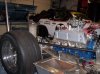
Thanks guy, I appreciate the kudos but to be honest I don't have a lot to do with it, yet. Getting this stuff setup is pretty easy and most of the ease of it is due to the chassis. A mono ally chassis really makes life easy as well as the car light. While looking at it yesterday we thought it a shame to have an iron block in there, but so it goes.

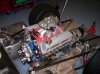
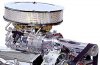
Wish I could promise it'd stay nice, but this is to be a working car and it'll probably end up looking like hell, as well as have numerous holes here and there and things get mounted and removed. Tis okay, it'll look good at 12 feet or 12 beers, whichever comes first. Malcolm, if we're going to have a scoop with it a la Mad Max it absolutely must have a blower too, this is a good one. What you think about driving that?

More work planned today - front of car, pedal remount, radiator remount, etc. Hope to have something worth viewing. Jeff and I also got the Miata cleaned up for sale yesterday too, couple hours, so new pics of that on the sale thread. Oh, and have to get the Jensen ready for the dyno later this week - new exhaust, carb balancing, turning, and raise the motor 1". I've a lot to do, best get busy!
 

Attachments

  • 51077144CSBP.jpg
    51077144CSBP.jpg
    31.1 KB · Views: 1,007
Back
Top