Long time no post, I hope you are all well.
Guidance or comments welcome for my judder issue. DAX 40, Ford 302 with Essex V6 Flywheel and 9"- 9 1/2" Borg and Beck. to UN1 transaxle.
Back in 2014, I drove the DAX 40 down to Goodwood for the weekend with Classic Car Tours.
Had a great time but on the way back about Birmingham the clutch release bearing disintegrated.
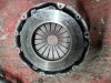
Flywheel and clutch body were in good condition, but I needed to replace the ring gear and reface the clutch plate.
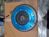
The old graphite release brg was replaced with a ball thrust brg.
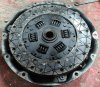
The existing clutch plate was refaced with Kevlar friction faces.
Also I replaced the original bronze centering bush with a roller brg.
Wind forward the transmission has been great until the last couple of years when at some point it developed a judder, only when taking off in 1st.
Apart from that, gearchange was absolutely normal with no vibration.
The judder was sufficient to make me change to a very gentle take off virtually on tickover, once rolling I could drive as normal.
I became suspicious that the roller bearing had failed and so I have removed transaxle and clutch for inspection.
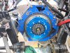
Everything seems ok, the roller bearing and release bearing spin freely, there is no debris or signs of wear on clich or flywheel.
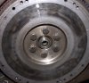
The only things I can see are a little bit of contamination with moly grease from the starter gear, and heat markings on the flywheel face.
There are no signs of seal leaks etc.
The flywheel face heat markings are a bit peculiar, but there is no significant wear as it feels perfectly smooth with no discernible ridge.
The heat markings could be pre-judder as after I installed EFI I went for a test drive but could only start off with third gear and that got the clutch stinking hot, but after gearshift adjustment it was fine.
So I'm a bit confused as it was fine before, and it's just a bog standard 9"- 9 1/2" Borg and Beck.
I briefly checked the engine mounts, they are ok and not old anyway.
I will clock the flywheel and test for distortion and flatness.
Depending on results I may stone or reface or replace.
I will check the input shaft diameter.
I wonder if it could be a drive shaft issue, so should look into that also.
Thanks in advance for any guidance or comments.
Guidance or comments welcome for my judder issue. DAX 40, Ford 302 with Essex V6 Flywheel and 9"- 9 1/2" Borg and Beck. to UN1 transaxle.
Back in 2014, I drove the DAX 40 down to Goodwood for the weekend with Classic Car Tours.
Had a great time but on the way back about Birmingham the clutch release bearing disintegrated.
Flywheel and clutch body were in good condition, but I needed to replace the ring gear and reface the clutch plate.
The old graphite release brg was replaced with a ball thrust brg.
The existing clutch plate was refaced with Kevlar friction faces.
Also I replaced the original bronze centering bush with a roller brg.
Wind forward the transmission has been great until the last couple of years when at some point it developed a judder, only when taking off in 1st.
Apart from that, gearchange was absolutely normal with no vibration.
The judder was sufficient to make me change to a very gentle take off virtually on tickover, once rolling I could drive as normal.
I became suspicious that the roller bearing had failed and so I have removed transaxle and clutch for inspection.
Everything seems ok, the roller bearing and release bearing spin freely, there is no debris or signs of wear on clich or flywheel.
The only things I can see are a little bit of contamination with moly grease from the starter gear, and heat markings on the flywheel face.
There are no signs of seal leaks etc.
The flywheel face heat markings are a bit peculiar, but there is no significant wear as it feels perfectly smooth with no discernible ridge.
The heat markings could be pre-judder as after I installed EFI I went for a test drive but could only start off with third gear and that got the clutch stinking hot, but after gearshift adjustment it was fine.
So I'm a bit confused as it was fine before, and it's just a bog standard 9"- 9 1/2" Borg and Beck.
I briefly checked the engine mounts, they are ok and not old anyway.
I will clock the flywheel and test for distortion and flatness.
Depending on results I may stone or reface or replace.
I will check the input shaft diameter.
I wonder if it could be a drive shaft issue, so should look into that also.
Thanks in advance for any guidance or comments.