Dusty's SLC Build

Ken Roberts

Supporter
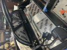
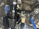
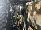
The radiator cap/ surge tank should be on the low pressure side of the cooling system (after the radiator). Your planned location unfortunately is the high side flow. The experts mention that during high engine rpm the pressurized radiator cap could eject coolant if installed on the high pressure side.
In my opinion that current tank would impede the flow of coolant to the radiator. I don’t see its purpose. I would still convert it to a surge tank but plumb it over to the passenger side low pressure coolant flow. Install a tee in the hose coming out from the 3/4” nipple and then run it over to a 3/4” hose barb at the bottom of the surge tank.
 
Last edited:
Thanks ken. I knew it looks kind of weird when I came by to see the car. your explanation makes total sense. should have spent a little time with the builder discussing this. No worries. Will get it fixed
 

Howard Jones

Supporter
Leave it where it is and re-route the plumbing.

First, the big pipe, the driver's side, from the radiator needs to go to the thermostat housing (hot out). Cut the tubing stub off the tank and weld a plate with an AN-8 male bung on it in its place. The AN-8 line should go to the inlet to the water pump inlet (cold side in from the radiator).

Next cut off the other tubing stub and weld a blank plate over the right side big hose output from your expansion tank. Add two small AN-4 bungs high on the tank, These are going to be the bleed lines from the engine top and the radiator top.

Now run the passenger side big pipe to the inlet to the water pump. Add AN-8 male bung to the tubing right at the end of the PS pipe before the hose connector piece. Connect the two AN-8 ports with a length of hose. This is the expansion tank connection to the coolant volume in the coolant system.

Lastly, add a fill neck for your radiator cap to the top of the tank.

Note: You will need to run an additional AN-4 line from the top of your radiator down the DS side pod to one of the two AN-4 ports on the expansion tank. You will need to select an appropriate location on your motor to bleed air from. I have not studied an LS enough to tell you where that is but I expect it is high on the intake manifold. where it needs to be to collect air in the engine. Run another AN-4 line from here to the other AN-4 port on the expansion tank.

Done
 
Last edited:
Thanks fellas. i just spoke to the fab man. i think we can leave the tank where it is. fab guy is going to redoo the tank. ill run it to the "low pressure side" heater hose like others do. he will also do the 4an ports up high on the tank for the heads and radiator.
thanks again

ill stuff an overflow tank in there someplace
 

Ken Roberts

Supporter
Dusty……keep the surge tank away from the bulkhead. It will want to bow out when it gets hot. You want to allow it to flex a bit and keep the heat from migrating into the bulhead. Use some standoffs when mounting it to the bulkhead. I pimped mine up a bit with carbon fibre stand offs. You could mount an overflow tank similar to mine in that location.

image.jpg
 
Last edited:
dang. didnt think about the problem of having a heater always sitting by me head. i just forwarded that to the builder.
 

Howard Jones

Supporter
As an aside. The water temp in the expansion tank is among the coolest things in the engine room. I might suggest you focus on an efficient barrier material for the whole firewall behind your head as well as the lower bulkhead between the engine and the fuel tank. I have used material like this this a lot and it works. It is available from many sources and in many thicknesses up to 1/2" thick and it gets more expensive the thicker it gets. More is better to a point. But the thick stuff can sag over time. The temps you will see at the bulkhead behind your head are fairly low with good airflow through the engine room and 1/16 " thick or less should work well enough.


or:


You could also add a 1/8" thick plywood shim between the bulkhead and the back of the tank under the insulation material to act as additional insulation. Just cut it out to fit the back of the tank RTV it to the aluminum bulkhead first and then bolt through it from the inside. It will act as a stud retainer and you will never know it's there. Simple. light, effective, and easy.
 
Last edited:
Still on it
Tank mounted
Firewalls complete. Every seam on firewall is sealed with high heat black silicone or the black aluminum tape
 

Attachments

  • IMG_3326.jpeg
    IMG_3326.jpeg
    434.7 KB · Views: 72
Sorry, I tried to post yesterday, but the pics were too big with my new camera. Took me a whole day to figure out how to make the picture smaller. It’s easier to build a car to take pics with an iPhone.

Anyway, this is the firewall basically like everyone else did
 

Attachments

  • IMG_3350.jpeg
    IMG_3350.jpeg
    563.4 KB · Views: 45
  • IMG_3351.jpeg
    IMG_3351.jpeg
    544.4 KB · Views: 50
I’ve had great luck with racepak in the past and so I am going to use it on this card. I am using Race pack sensors:
Oil pressure
Fuel pressure
Water temperature
Transaxle temperature

The specific sensors I’m using are a Race pack specific pre-labeled sensors called “v net sensor modules”
These particular sensors come pre-labeled from Race back. You simply plugged them together in a chain and plug the chain directly into your Smart, wire control module. That module is what controls all of your switching with solid-state. no breakers no fuses. And the smart wire connects to your dash system with one wire.

Over the years race pack has simplified the system by offering pre-labeled wiring harnesses that are plugged and play. You just connect the pre labeled wires from the switching module to your electrical equipment. Because the wires are pre-labeled you don’t need to assign them names in the software. This convenience just simplifies the entire process.
 

Attachments

  • IMG_3358.jpeg
    IMG_3358.jpeg
    264.7 KB · Views: 41
  • IMG_3357.jpeg
    IMG_3357.jpeg
    318.4 KB · Views: 40
  • IMG_3355.jpeg
    IMG_3355.jpeg
    363.5 KB · Views: 44
  • IMG_3353.jpeg
    IMG_3353.jpeg
    313 KB · Views: 40
You can see here that the supplied wiring harnesses have pre-labeled wires that are automatically recognized by the switching module and the dash so that you don’t have to label these particular things when you want to program switching parameters.

You can also see that I have two type of Switching options. One is the digital – switching pad, and the other here is so that I can run my own switches. When you run your own switches, it’s a little bit more work because you didn’t need to program and identify them with the software another option not shown here is to use Race pack, specific toggle switches
I’ve included a picture from my rock racer so that you can see with those are like
 

Attachments

  • IMG_3360.jpeg
    IMG_3360.jpeg
    489.6 KB · Views: 41
  • IMG_3361.jpeg
    IMG_3361.jpeg
    390 KB · Views: 38
  • IMG_3362.jpeg
    IMG_3362.jpeg
    601.3 KB · Views: 38
  • IMG_3365.jpeg
    IMG_3365.jpeg
    266.1 KB · Views: 45
I am going to be using the race pack. GPS module to keep track of my speed

Note that on this car, and on my prior project, I run the race pack supplied engine monitoring sensors in parallel to the engine sensors that came with the crate engine, and are recognized by the factory ECU to help the engine run properly . Race Pack does make solutions that let you Utilize the OBD2 port so that you can capture the sensor data being seen by your ECU and then transfer that data via the OBD port to your race pack monitor. It is then possible to use that information to control switching scenarios. (Like once the ignition is turned on the fan is turned on at a specific engine temp)

I just don’t want to spend a bunch of time identifying and labeling these telemetry points from the factory ECU, and then integrating them into my own switching decisions. I don’t want to be working through those painfull computer issues so I just plug and play parallel race pack prelabeled sensors. (again it took me a day to figure out how to make the phone pictures smaller)

Anyway, I’m just about ready to start the car. Of course every time I say something like that a month goes by.
 

Attachments

  • IMG_3366.jpeg
    IMG_3366.jpeg
    367.3 KB · Views: 48
I admittedly wonder how much this transaxle cooler will make a difference. There is no fan on it and it’s not that big overall. Fortunately, this bracket I am using for the cooler is very easy to modify. It simply unbolt, and I can add an and I can add a larger cooler as data comes in. And with the temperature gauge on the transaxle line, I can use that sensor as a switch through my smart wire module to potentially turn on a fan for the transaxle I want to.

You will also notice that the wires from the Smart wire have large gauge wires to potentially run the fan directly off the smart wire. Once I see how many amps I’m going to be pulling I might not run relays, but I did run relays on the Rok race car because in the rock racer situation I am running a lot more fans (two transmission fans, and two large radiator fans, and lots of lights and a large winch ) and a lot more electronics and so I was above the amperage capacity of the switching module and needed the relays but we shall see.
 
I forgot this thing. This is the little device that lets you wire in your own switches to the race pack. You simply wire in your specific switch and then this device plugs into your switching module and into the dash. once you have wired in your own switches you can go ahead and label them do the software on the switching module and utilize the switches. This sort of switching option could be used for switches that you already had in the car or for switches you might want to put on the steering wheel . You could also use the switches for for stuff like the flames that go out the tailpipe, machine guns, lasers, etc.
 

Attachments

  • IMG_3367.jpeg
    IMG_3367.jpeg
    438.7 KB · Views: 46
Back
Top