

You are using an out of date browser. It may not display this or other websites correctly.
You should upgrade or use an alternative browser.
You should upgrade or use an alternative browser.
Frank's KVA Build
- Thread starter Frank Beuker
- Start date

Re: frank's kva
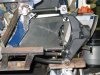
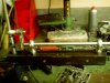
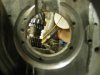
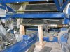
started working on the frontend
going to change the position of the steeringrack to provide room for the pedalbox witch i'm making because i can't use a standard standing pedalbox
started working on the frontend
going to change the position of the steeringrack to provide room for the pedalbox witch i'm making because i can't use a standard standing pedalbox
Attachments
Re: frank's kva
hoi willem,
i shall post some tonight
eddie just give me a call my number is 0654271113 i'm working on my car tonight and tommorow the hole day and leiden is as you say nearby
what are you building?
frank
hoi willem,
i shall post some tonight
eddie just give me a call my number is 0654271113 i'm working on my car tonight and tommorow the hole day and leiden is as you say nearby
what are you building?
frank
Re: frank's kva
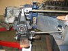
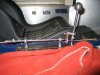
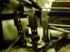
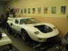
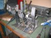
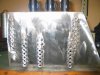
he're some pictures of the total car and the almost finished pedalbox
he're some pictures of the total car and the almost finished pedalbox
Attachments
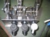
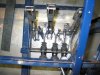
steeringrack
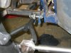
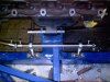
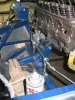
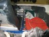
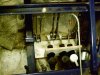
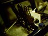
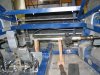
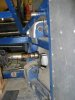
working on the positioning of the steeringrack
i positioned it now so the joint's are in the same line as the joint's from the upper and lower arms
I've searched on the forum about the positioning and there is a lot been written about that subject can anyone be of some assistance with this subject and in simple english because altough i can read resonable tecnicle english my vocab is lost on this subject
frank
Attachments
Ian Anderson
Lifetime Supporter
Re: frank's kva
I did have a look but can't find any specific's
frank
I did have a look but can't find any specific's
frank
Doc Watson
Lifetime Supporter
Re: frank's kva
I assume you are trying to eliminate any bump steer.
Bump Steer is when your wheels steer themselves without input from the steering wheel. The undesirable steering is caused by bumps in the track interacting with improper length or angle of your suspension and steering linkages.
As the car passes over a bump in the road the change in suspension height of the front wheel can cause the wheel to 'steer' in or out depending on the geometry of your suspension.
The perfect position for the steering rack and tie rod length will result in no 'steering' effect of the front wheels when the suspension is compressed or extended (unloaded), this is known as zero bump steer.
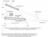
(Sorry this is where it gets a little technical......the picture will help...)
In order to accomplish zero bump the tie rod must fall between an imaginary line that runs from the upper ball joint through the lower ball joint and an imaginary line that runs through the upper a-arm pivot and the lower control arm pivot. In addition, the centerline of the tie rod must intersect with the instant center created by the upper a-arm and the lower control arm.
The instant center is an imaginary point that is created by drawing a line from the upper a-arm ball joint through the a-arm pivot where it is intersected by an imaginary line that extends from the lower ball joint through the inner control arm pivot. Where the two imaginary lines intersect is the instant center.
To achieve zero bump the front end must be designed correctly. The tie rod must travel on the same arc as the suspension when the car goes through travel. Simply matching lengths and arcs to prevent any unwanted steering of the front tires.
To exaggerate, if the tie rod were only 10" long and the suspension were 20" long then when the suspension traveled the tie rod angle would shorten much quicker than the suspension arc. In this scenario the tie rod would shorten much quicker through travel than the suspension and the car would toe in drastically over bumps. The shorter arc of the tie rod would pull on the spindle and toe it in through travel.
To prepare your car for bump steer.....
Your front suspension must be complete and set for racetrack conditions before you can measure the bump steer. All components must be tight and in proper position, a quality bump steer gauge is advisable to set up the suspension.
1
Set the car at ride height.
2
Use the proper size tires and air pressures.
3
Caster must be set.
4
Camber must be set.
5
Toe in must be set.
6
Tie rod lengths must be set.
7
Steering should be centered (tie rod ends centered on inner pivot points lower ball joints).
8
Steering must be locked down.
9
Measure from the ground to the lower ball joint or other reliable reference point. Write the number down.
10
Remove springs and disconnect the sway bar (if you have one).
11
Return the suspension to the proper height by using your reference number to the ground.
12
Bolt on the bump steer plate to the hub. Level the plate and note where the dial indicator is on the bump steer plate so that you can quickly return to the correct ride height.
13
Jack the suspension through 2"-3" of both compression and rebound travel and write down your results.
14
Shim as needed (see below)
Making Bump Steer Corrections
Now that you have measured your bump steer you will need to adjust, shim or relocate the suspension components to get the exact reading that you desire.
Symptom 1. Toes out in compression and in on rebound all in one direction. Cure 1. Decrease shim on outer tie rod or lower the inner tie rod.
Symptom 2. Toes in on compression and out in rebound all in one direction. Cure 2. More shim at outer tie rod or raise the inner tie rod.
Symptom 3. Always toes in both compression and rebound. Cure 3. Lengthen the tie rod as it is too short.
Symptom 4. Always toes out on compression and rebound.
Cure 4. Shorten tie rod as it is too long.
Symptom 5. Toes out on compression, then in on rebound and then starts back towards out with more rebound travel.
Cure 5. Less shim at outer tie rod and shorten tie rod.
Symptom 6. Toes in on compression, then moves out on rebound and then starts back towards in with more rebound travel.
Cure 6. More shim at outer tie rod and lengthen tie rod.
I hope this makes sense... and it really does need a bump steer gauge to do it accuratly.
Extract from...
Bump Steer
Hope this helps
I assume you are trying to eliminate any bump steer.
Bump Steer is when your wheels steer themselves without input from the steering wheel. The undesirable steering is caused by bumps in the track interacting with improper length or angle of your suspension and steering linkages.
As the car passes over a bump in the road the change in suspension height of the front wheel can cause the wheel to 'steer' in or out depending on the geometry of your suspension.
The perfect position for the steering rack and tie rod length will result in no 'steering' effect of the front wheels when the suspension is compressed or extended (unloaded), this is known as zero bump steer.
(Sorry this is where it gets a little technical......the picture will help...)
In order to accomplish zero bump the tie rod must fall between an imaginary line that runs from the upper ball joint through the lower ball joint and an imaginary line that runs through the upper a-arm pivot and the lower control arm pivot. In addition, the centerline of the tie rod must intersect with the instant center created by the upper a-arm and the lower control arm.
The instant center is an imaginary point that is created by drawing a line from the upper a-arm ball joint through the a-arm pivot where it is intersected by an imaginary line that extends from the lower ball joint through the inner control arm pivot. Where the two imaginary lines intersect is the instant center.
To achieve zero bump the front end must be designed correctly. The tie rod must travel on the same arc as the suspension when the car goes through travel. Simply matching lengths and arcs to prevent any unwanted steering of the front tires.
To exaggerate, if the tie rod were only 10" long and the suspension were 20" long then when the suspension traveled the tie rod angle would shorten much quicker than the suspension arc. In this scenario the tie rod would shorten much quicker through travel than the suspension and the car would toe in drastically over bumps. The shorter arc of the tie rod would pull on the spindle and toe it in through travel.
To prepare your car for bump steer.....
Your front suspension must be complete and set for racetrack conditions before you can measure the bump steer. All components must be tight and in proper position, a quality bump steer gauge is advisable to set up the suspension.
1
Set the car at ride height.
2
Use the proper size tires and air pressures.
3
Caster must be set.
4
Camber must be set.
5
Toe in must be set.
6
Tie rod lengths must be set.
7
Steering should be centered (tie rod ends centered on inner pivot points lower ball joints).
8
Steering must be locked down.
9
Measure from the ground to the lower ball joint or other reliable reference point. Write the number down.
10
Remove springs and disconnect the sway bar (if you have one).
11
Return the suspension to the proper height by using your reference number to the ground.
12
Bolt on the bump steer plate to the hub. Level the plate and note where the dial indicator is on the bump steer plate so that you can quickly return to the correct ride height.
13
Jack the suspension through 2"-3" of both compression and rebound travel and write down your results.
14
Shim as needed (see below)
Making Bump Steer Corrections
Now that you have measured your bump steer you will need to adjust, shim or relocate the suspension components to get the exact reading that you desire.
Symptom 1. Toes out in compression and in on rebound all in one direction. Cure 1. Decrease shim on outer tie rod or lower the inner tie rod.
Symptom 2. Toes in on compression and out in rebound all in one direction. Cure 2. More shim at outer tie rod or raise the inner tie rod.
Symptom 3. Always toes in both compression and rebound. Cure 3. Lengthen the tie rod as it is too short.
Symptom 4. Always toes out on compression and rebound.
Cure 4. Shorten tie rod as it is too long.
Symptom 5. Toes out on compression, then in on rebound and then starts back towards out with more rebound travel.
Cure 5. Less shim at outer tie rod and shorten tie rod.
Symptom 6. Toes in on compression, then moves out on rebound and then starts back towards in with more rebound travel.
Cure 6. More shim at outer tie rod and lengthen tie rod.
I hope this makes sense... and it really does need a bump steer gauge to do it accuratly.
Extract from...
Bump Steer
Hope this helps
Attachments
Re: frank's kva
thank's this will of help
i've orderd new upright from john wisher so i can determen where ever i want to put the connectionpoint for the tierod
is there a rule for the position of the rack (to the front or back)
frank
thank's this will of help
i've orderd new upright from john wisher so i can determen where ever i want to put the connectionpoint for the tierod
is there a rule for the position of the rack (to the front or back)
frank
Doc Watson
Lifetime Supporter
Re: frank's kva
I dont think it will make to much difference for the front to back position....
Just keep with the rules on the diagram above.
Anybody else help here?
I dont think it will make to much difference for the front to back position....
Just keep with the rules on the diagram above.
Anybody else help here?
Re: frank's kva
i will thank's
i will thank's
Similar threads
- Replies
- 5
- Views
- 978
- Replies
- 10
- Views
- 3K