Frank's KVA Build

first upper arm almost ready
first made a welding mould ,did bend the tube (yes decided to do it myself )
i already made the tubes for the sphearical bearing
hope to have the front arms ready by the end of the week (try to work every evening)
i'll keep on posting as i progress
 

Attachments

  • IMG_2813 (Small).jpg
    IMG_2813 (Small).jpg
    53.3 KB · Views: 1,038
  • IMG_2814 (Small).jpg
    IMG_2814 (Small).jpg
    56 KB · Views: 1,038
  • IMG_2815 (Small).jpg
    IMG_2815 (Small).jpg
    90.1 KB · Views: 1,023
  • IMG_2816 (Small).jpg
    IMG_2816 (Small).jpg
    92 KB · Views: 1,021
  • IMG_2817 (Small).jpg
    IMG_2817 (Small).jpg
    62.6 KB · Views: 1,083
hi frank you are doing a nice job. keep on welding..... and we can drive our cars at the same time next summer
 
Frank;
Nice looking work.
I hope you don't mind if I make a few suggestions to possibly help a little.

I see the cross shaft in your fixture looks nice and solid..try to index the center sleeve so that your repeatability is there, and also if it needs to be moved in the future to create more or less caster.
If you use a rod end at the top of your upright you can shim it up or down to change virtual swingarm length and roll center...I have seen some high misalignment rod ends that will go 24 deg., plenty enough for full travel.
Please understand I am not criticizing here just throwing a few hints your way....your work looks great and the finished product should be good looking as well as strong the way you are progressing.
Cheers
Phil
 
Last edited:
Hi Phil as i always say any help is welcome
i'will post a picture as it is going to be and if you can try to explain again what you mean because i don't get the picture

Frank
 
pictures with the balljoint and the bottompicture is a original upper arm
 

Attachments

  • IMG_2818 (Small).jpg
    IMG_2818 (Small).jpg
    89.2 KB · Views: 965
  • IMG_2819 (Small).jpg
    IMG_2819 (Small).jpg
    66.9 KB · Views: 970
  • IMG_2820 (Small).jpg
    IMG_2820 (Small).jpg
    72.7 KB · Views: 964
  • IMG_2821 (Small).jpg
    IMG_2821 (Small).jpg
    62.7 KB · Views: 953
  • IMG_2822 (Small).jpg
    IMG_2822 (Small).jpg
    39.8 KB · Views: 963
  • IMG_2823 (Small).jpg
    IMG_2823 (Small).jpg
    38.9 KB · Views: 953
Frank;
Sorry if I was not so clear, but what I was saying was to lock your center part of the fixture that locates the threaded sleeve for the upper joint, and if you can make sure it goes in the same place when making the opposite side. I have a fixture patterned after an original set of uppers, and it can be moved to fab arms that will add some more initial caster as some of the cars could not achieve enough by sliding the arm rearward..they simply hit the mounts on the tub.
Also I see your are using an upper ball joint similar to a tie rod end which has a taper bolt which is a nice fit but doesn't allow shimming to tune the roll center. I was suggesting a taper bolt for the upright, with a straight shaft on the other side. This will allow the use of a rod end which can be shimmed up or down to change your roll center. Maybe it would be easier if I posted a couple of photos?. I am working on a front end right now and I could take some photos and post them tommorrow (Thurs. for me).
 
upper arm fitted
also pictures of the camberadjustment min and maximum
 

Attachments

  • IMG_2824 (Small).jpg
    IMG_2824 (Small).jpg
    69.5 KB · Views: 922
  • IMG_2825 (Small).jpg
    IMG_2825 (Small).jpg
    44.4 KB · Views: 887
  • IMG_2827 (Small).jpg
    IMG_2827 (Small).jpg
    40.3 KB · Views: 900
  • IMG_2828 (Small).jpg
    IMG_2828 (Small).jpg
    41.9 KB · Views: 882
Frank:
Sorry about the delay but I managed to delete all the photos I took while uploading from the camera..pot verdomme! But have them now.
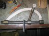
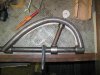
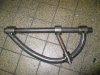
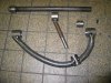
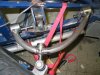
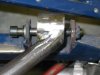
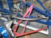
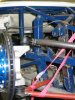
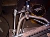
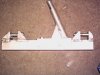
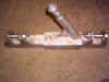
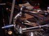
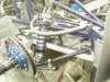
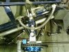
What I was trying to say was to make sure that you have your fixture set so that you can repeat the arm with reasonable accuracy..locking that center sleeve for example, but also having the flexibility to move it rearward to add more built in caster as sometimes there is not sufficient travel within the mounts to accomplish this...I am posting a photo of my fixture, and it has a slider on it to accomplish this.
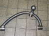
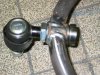
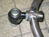
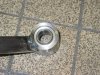
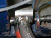
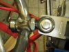
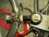
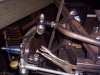
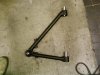
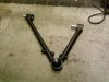
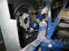
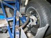
Also, I use a monobolt in the top of the upright...the photos I am sending show a plain bolt for now on a new chassis we are constructing, but the idea is the spherical part of the joint can be raised or lowered to change swingarm length and therefore roll center. Also using a rod end at the steer arm, which can be spaced up or down is helpful in resolving bump steer issues.
I think it is great that you are fabbing your own stuff, its much more satisfying than just buying and bolting up, and I look forward to these kinds of posts.
Keep up the good work
Cheers
Phil
 

Attachments

  • PICT0004.jpg
    PICT0004.jpg
    55.7 KB · Views: 841
  • PICT0006.jpg
    PICT0006.jpg
    63.6 KB · Views: 859
  • PICT0007.jpg
    PICT0007.jpg
    65.8 KB · Views: 843
  • PICT0001.jpg
    PICT0001.jpg
    58.2 KB · Views: 880
  • PICT0002.jpg
    PICT0002.jpg
    59.1 KB · Views: 878
Phil looks great I think we both got the same vision i've got enough space for setting the caster i'm at the moment more busy with the track at the front and the clearence within the front clip
Frank
 
Frank
Thanks
If you have any issues give me a PM as I have that front end pretty well sorted, and if I can speed you along I will.
Cheers
Phil
 
some pictures of the progress i made butt i onley had my phone with me so the pictures aren't that great
 

Attachments

  • SP_A0035.jpg
    SP_A0035.jpg
    52.2 KB · Views: 679
  • SP_A0036.jpg
    SP_A0036.jpg
    57.2 KB · Views: 688
  • SP_A0037.jpg
    SP_A0037.jpg
    58 KB · Views: 704
  • SP_A0038.jpg
    SP_A0038.jpg
    64.5 KB · Views: 679
The car is standing on its own wheels again since 2 years
the front finaly all the parts fitted and test wealded
next thing is caster and then steeringarms
 

Attachments

  • IMG_2836 (Small).jpg
    IMG_2836 (Small).jpg
    52.9 KB · Views: 599
  • IMG_2837 (Small).jpg
    IMG_2837 (Small).jpg
    66.5 KB · Views: 609
  • IMG_2838 (Small).jpg
    IMG_2838 (Small).jpg
    21.7 KB · Views: 570
Frank
Great looking job there. You mentioned that you were going to add caster to the front end, it looks like you have plenty of room to move your upper wishbone rearward in the mounts, and I can tell you that as you add caster the camber will go towards positive so you will have to bring that upper joint pretty far in to get the neg. camber set.
A guy recently stopped by my shop and was critical of the amount of thread showing at the upper joint on my suspension...about 3/4 inch, but that was at zero caster. I could tell he wasn't familiar with the setup, and when I dialed in about 4 deg. of positive caster I had enough thread to add neg. camber of 1 deg. with 3 or 4 threads showing...about what I was looking for although I may add another deg. of caster, there is definitely enough room on the link and the mounts.
Keep the photos coming...looks great.
Cheers
Phil
 
If you use 'Spherical' bearing/bush's or rod ends at the inner pivots of your wishbones you could align the inner pivot brackets/bolts on the chassis as per the 'Top' attached dwg so rearward shift of the top w/bone for more castor would have very little if any effect on the camber angle.

Jac Mac. ( Yeah, I know, Now he tells us- Sorry guys, its only because I have been trying to work out a solution for my own car in my head while working on other stuff - at least I am happy now:))
 
Last edited:
Thanks Phill

Jac Mac,
I Knew that butt wanted to keep the 'original' look so i went for spherical bearings inside the arms and not the rodends

I've got plenty of caster already but only need to find a easy way of measuring it to see if it's the same on the left and right and if it's not to much so any idear's ????
all help is welcom.
I want to measure the caster before going to work on my steering arms
 
Frank, If you have or can borrow a 'Smart Level' with digital readout to measure your camber angle you can calculate the castor angle by measuring the Camber angle @ approximately 20° left and right steering lock. The castor angle will be the difference between the two readings ( Remember to allow for the possibility of the wheel developing positive or negative readings at these steering angles; for example on RH wheel you may get say +6° on RH lock & -1° on LH lock- this would mean you had 7° castor------ if the readings are +8° RH lock & +2° LH lock you have 6° castor ).

Also Randy ( Big Foot ) had a cunning trick for turntables to allow setting up stuff like this- two floor tiles with grease between them to allow the car to move freely.

Jac Mac
 
Back
Top