Ken's SLC build thread

Ken Roberts

Supporter
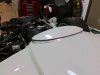
Ken, very classy! I love the 3rd. brake light, it truly looks like it belongs there!
Jim

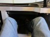
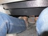
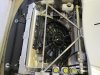
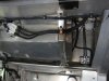
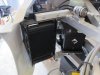
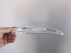
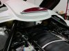
Thanks Jim! Here is a picture of the intermediate plate that had to be made (not finished yet) to take up the different profiles. The bottom of the brake light is flat while the top of the spider is curved. It's shaped out of aluminum.
 

Attachments

  • 018_zps6b2c1757.jpg
    018_zps6b2c1757.jpg
    11.7 KB · Views: 247
  • 018_zps9b8701ac.jpg
    018_zps9b8701ac.jpg
    26.8 KB · Views: 263
  • 019_zpsf71e218b.jpg
    019_zpsf71e218b.jpg
    37.8 KB · Views: 226
Last edited:
Ken. Not sure if dot approved but I used led license plate bolts on my mini project that are tiny and worked for that. Cost like $5-10 on eBay.
 

Ken Roberts

Supporter
Ken. Not sure if dot approved but I used led license plate bolts on my mini project that are tiny and worked for that. Cost like $5-10 on eBay.

That would have been perfect. Unfortunately the inspection here in my province is difficult. All lighting must be DOT/SAE approved.:cry::furious:
 
Ken hope you dont mind the thread drift but I was at Katech today checking out this little beauty....can you guess what car its for?
 

Attachments

  • katech slc engine.jpeg
    katech slc engine.jpeg
    225.6 KB · Views: 827

Ken Roberts

Supporter
Here is a couple of pictures of the installed AC evaporator. You can see that there is no interference with the legs, knees, shins or feet. Getting in and out of the passenger seat is exactly the same whether the AC evaporator is installed or not.
 

Attachments

  • 002-8_zps5c9a5b50.jpg
    002-8_zps5c9a5b50.jpg
    40.1 KB · Views: 268
  • 008-1_zps00f86ec5.jpg
    008-1_zps00f86ec5.jpg
    41.4 KB · Views: 215
Last edited:

Ken Roberts

Supporter
For anybody needing the pinouts for the XLR steering column ...here they are:
 

Attachments

  • Steering1.jpg
    Steering1.jpg
    99.1 KB · Views: 200
  • Steering2.jpg
    Steering2.jpg
    113.1 KB · Views: 205
  • Steering3.jpg
    Steering3.jpg
    98.8 KB · Views: 182
Last edited:

Ken Roberts

Supporter
Back to working on the car after a much needed break. Here is a picture of the vents being cut out on the rear wheel tubs.
 

Attachments

  • 002_zpsf99c3eb6.jpg
    002_zpsf99c3eb6.jpg
    50.5 KB · Views: 222
Last edited:

Ken Roberts

Supporter
The radiator was successfully isolated from the rest of the structure. The fiberglass nose body work still fits. Even the Corvette fan shroud is not touching the rad. A high temp bulb seal will be fitted to the edge of the fan shroud to take up any gaps.
 

Attachments

  • 009_zps75a39b52.jpg
    009_zps75a39b52.jpg
    47.6 KB · Views: 221
Last edited:

Ken Roberts

Supporter
Here is the completed fuel system. The three nylon lines at the fuel bucket module in the tank carry the fuel to and from the C5 Corvette filter regulator and vapors to the evap tank. The filter/regulator than delivers the fuel to the rails. This line is Aeroquip stainless braided teflon. There is only one 90 degree fitting in the whole setup.

The fuel tank is only held in place with two traditional style of stainless steel straps.

In the second picture you can see where the battery is mounted. The bracket is slightly elevated so that the hand brake cables can travel underneath it.
 

Attachments

  • 002_zpsm7xgfbal.jpg
    002_zpsm7xgfbal.jpg
    110.9 KB · Views: 223
Last edited:

Ken Roberts

Supporter
A tunnel was made to force all the flow of air through the transaxle cooler and not around it for efficient operation. You can also see the C5 fuel filter/regulator, the battery and OEM shaved down Corvette battery tray and in front of the cooler you can see the C6 Corvette Evap canister.
 

Attachments

  • 002_zpsed332704.jpg
    002_zpsed332704.jpg
    37.6 KB · Views: 213
Last edited:
Back
Top