M20 Dreaming

Terry Oxandale

Skinny Man
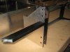
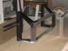
Great post Russ. So in essence, a robust crush-tube is welded perpendicular to the hoop stem tube, and this crush tube then bolts onto the base via a tapered fit. This configuration seems to be a bit "complex" when one can get away with welding a plate on the base of the hoop and simply bolt it in place (or have I missed something?).

So...has Russell built the entire hoop crossbars and rear braces as a single unit, and then used the above attaching method to bolt this assembly to the frame tubes? If so, doesn't this turn a compressive force (landing on it's back) into a shear force of the tubing itself? I feel I'm being very dense here.

standard.jpg


Or is it like the drawing below. Even so, the frame tube would seem to require reinforcement tubing (to distribute loads) right at the point where the crush-tube is welded into the chassis tubing.

standard.jpg


or:

standard.jpg
 
Last edited:

Keith

Moderator
Fascinating thread guys.. As a matter of interest only as cost would be a huge issue, the guys at Lotus cars use adhesive to bind their Elise & Exige monos as I'm sure you know.

The adhesive is a single-part, heat-cured epoxy paste (XB 5315) which is more often used tar bonding oily steel. It has a tensile strength of 35 MPa and an E-modulus of 2,700 MPa. Curing takes about 40 minutes at 200°C. Until cured, it has a paste-like consistency and is very stable.

I believe they have now had cars running as such since 1996 and I don't think there have been any failures at all. However the chassis does use over 25 parts specially extruded and designed for the bonding process.

Still, with 500+hp going through the Big Mac I'm sure you'll need all the help you can get! By the way Leon, what will you call the car?

Can't wait to see it run.... :)
 

Russ Noble

GT40s Supporter
Lifetime Supporter
Terry, basically no.

The base must be a metal foot to spread the loads (saloon car scenario really).

253-28 is for attaching removable members to the main roll bar. ie backstays etc. If you are keen enough to flick through Sch. A you will find all the relevant regs in there. None of which will affect you! However there are some different joining systems illustrated in the diagrams at the end.

I guess if you have no regs to comply with you can do whatever you think is best for your situation.
 
Russ K (and assorted interested kiwis only!) - I think you got lucky with the tech guys on the lower backstay mounts. I reckon your approach is neat, strong and fit-for-purpose, however the regs say hinge joints are specifically excluded in the principle structure, which is a defined term that includes the backstays. You give me some hope that I might be smiled upon by the MSNZ technical people and get a normal cage homologation after all! Cheers, Andrew
 
I see how Russel has done it now, But to be honest if I can't Bolt it the way Andrew has, which is how the orginal was done then I will just make it in one part and bolt the hoop to the Rear bulk head and the back stays to the engine block. the way its show with the tapered plug and cap srcew looks complicated and unessasary.

Kieth, I'm just going to call it a LM20Can-Am (Leon Macdonald 20) simple and it avoids the obvious problems. I HOPE.

Cheers Leonmac
 

Keith

Moderator
Kieth, I'm just going to call it a LM20Can-Am (Leon Macdonald 20) simple and it avoids the obvious problems. I HOPE.

Cheers Leonmac

Can't see any problems with that Leon. Good name :thumbsup:

By the by, I worked out of some offices in Croydon in the early 90's, and below these was a vast workshop at that time turning out flatpack furniture. On the end wall, was painted the complete history of McLaren racing team - results and races entered. I remember at that time thinking how I could preserve the wall or even photograph it! Sadly I did neither and lost track of the building when the company went bust in '93 - the building of which was then demolished and I guess the wall with it.

After a bit of homework I discovered that this was the old Trojan factory in another life, and it was there that all McClaren customer race cars were produced including the F5000, MGT6 road car and the early Can Ams at least up until the M8. Imagine! Right on my doorstep (I lived not 3 miles away)

What I don't know and would like to discover is whether the McLaren racing team factory cars were built there too. I would guess they were but don't know for sure. If they were, then whoever made the comment about the adhesive "coming from a store in NZ" was slightly off geographically, because it may have come from my local DIY store in Croydon Surrey! :shocked:

Some Lister Jags were also built/prepared just up the road, so an interesting industry right on my doorstep.. :)
 
Hi Kieth, I can tell you for sure that the factory cars were not built in the same factory as the Trojan cars. The first factory was at "David Road" this was late 64 and then they moved into a bigger factory on a new industrial unit not far from the old factory but the name escapes me at this point.
Leonmac
 
Hi again, the other factory was "Colinbrook" but to honest without checking my books at home I'm not sure wich one was first, I think the Ca-Am cars were built at "Colinbrook" Cheers Leonmac
 
Terry
I used the tapered joint drawing 253.28 to join the rear brace bars to the top of the roll cage. My attachment of the hoop is by the normal flat plate and bolts to a strenghthed chassis segment. I could have just welded up the braces but liked the look and practicality of the removable bars.
Cheers
 
Not sure if this will help your current roll bar-mount concerns, but everyone loves color pictures. LMP M1C chassis.
 

Attachments

  • 1171.jpg
    1171.jpg
    57.4 KB · Views: 587
  • 1168.jpg
    1168.jpg
    56.8 KB · Views: 1,759
Hi Joe, very nice chassis, That is how I want to mount my back stays to the hoop just not sure if the rules in NZ will allow it. but thanks for the input, I see you only have 3 posts so I'm guessing you are new to this forum. Welcome and don't be shy with ideas the guys on here are very open and share knowledge willingly. Are you going to start a Build log on your M1C it would be nice to see it develop.

Cheers Leonmac
 
Heres a curly one, (Back on adhesives) something I've been pondering if you glue an alloy panel to a painted surface is the bond only as strong as the paint bond to the metal surface, example, The rear bulkhead in my tub is steel and I will bond and rivet it into the alloy tub. Obviously I want to paint it to avoid corrosion (it is not seen once mounted in the tub) your thoughts Please. Leonmac.
 

Keith

Moderator
Only as strong as the paint bond Leon, and I would have thought that if you used an epoxy 2 part adhesive, that would be all the anti corrosion surface you would need (given that you have 'etch primed' the bonding surfaces). All else but the bonding surfaces could be paint.
 
Hi, I got home last week and did a bit on the lathe the other day, I have changed tact on the the rear upright bearing holder. The upright was difficuilt to hold in the the lathe and I wasn't 100% happy with the precision of the the maching so on the second unit I bored it out and pressed the steel housing which I machined from the orginal Nissan hub, so I know its perfectly machined. It took 15 ton to press the unit in so I don't think it will move but I may put a couple of grub screws in the side to be sure.
I bought my self an air rivet gun and the SR rivets the other day so may get some rivets done this time but will have to see how time goes. not sure how long I,m home for this time. I have finished in Oman and now waiting for a Visa for Angola so could be off at short notice. Cheers Leonmac.
 
Been doing some more work on the rear suspension this week. Last couple of days have resulted in the top rear subframe being fabbed up. I'm tring to keep it looking like the orginal so this has ment a lot of slicing and welding of the box section to get the angles. the front side brackets have a small hand beaten lip around the length where they are welded to the box section, these with smaller brackets on the back side will hold the top of the coil over and the mounts for the sway bar. Then I made the box like bracket that holds the top link, this also has a hand beaten lip around the edge to give it some strength. I still have to make the rear brace that will tie the hole thing up and give it a lot of strength. I have attached some photos, there is some finishing to be done to get it ready before painting so it may look a bit rough. Cheers Leon
 

Attachments

  • my pictures 008.jpg
    my pictures 008.jpg
    41.6 KB · Views: 511
  • my pictures 016.jpg
    my pictures 016.jpg
    38.3 KB · Views: 478
  • my pictures 017.jpg
    my pictures 017.jpg
    25.9 KB · Views: 467
  • my pictures 022.jpg
    my pictures 022.jpg
    32 KB · Views: 467
  • my pictures 026.jpg
    my pictures 026.jpg
    31.1 KB · Views: 510
Some more progress. I have now started to bond and rivet the tub and it feels like I'm making real progress now. I have double row rivets on the main bulk heads and down the sides of the cock pit, infact the only single row is where the outsides of the tub are riveted to the floor pan. All the rivets are at 1" spacing and the double rows are staggered and I have gone with the Sikaflex 221 for bonding. Doing the curved lip was achieved by cutting the curve in wood moulds and hand beating the edge to make the lip. I have also done the only steel bulkhead in the tub. This is what the rear suspension, engine mount and roll bar is attached to but once in the tub finished you won't see most of the steel work as it is covered by alloy. I have also brazed the suspenion arms and links now and have almost completed the rear top mount.
The next major fabrication items will be the side pods that hold the raidators, and the seat panels and centre spine which will give the tub its real strenght, then the front suspension mounts will be done before the dash panel and top is put on.
 

Attachments

  • Rear Subframe 001.jpg
    Rear Subframe 001.jpg
    35 KB · Views: 434
  • Rear Subframe 004.jpg
    Rear Subframe 004.jpg
    30.8 KB · Views: 399
  • Rear Subframe 007.jpg
    Rear Subframe 007.jpg
    32.8 KB · Views: 431
  • Rear Subframe 002.jpg
    Rear Subframe 002.jpg
    30 KB · Views: 417
  • Rear Subframe 003.jpg
    Rear Subframe 003.jpg
    28.5 KB · Views: 407
  • Rear Subframe 005.jpg
    Rear Subframe 005.jpg
    35.2 KB · Views: 421
  • Rear Subframe 006.jpg
    Rear Subframe 006.jpg
    37.1 KB · Views: 419
Back
Top