New front suspension for my RF

Chris Duncan

Supporter
The original arm is a pretty refined piece. Using spherical bearings for inner links straightens the load path more than is possible with rod ends.

The tubing is bent to get around the shock.

It's not shown in the drawing but on some cars the outer weld joint had a doubler.

Larger diameter tubing (1-1/8") negates the need for gusseting.
 

Attachments

  • 51945-UpArm.jpg
    51945-UpArm.jpg
    97.2 KB · Views: 296

Chris Duncan

Supporter
Trevor

"Flexure will be occur at the toe of the weld at the 090 tube"

You are correct. Your ideas give me more ideas which I will draw next time I have time. I know the upper arm carries less load than the lower due to shock mount point. If they are the same size tube less gusseting would be necessary. I wonder what the actual difference is in loading.

Richard,

there was a thread that discussed welding 4130 and the embrittlement issue. I believe it was about roll cages.
 

Trevor Booth

Lifetime Supporter
Supporter
Kalun, the load relationship upper vs lower is directly proportional to the distance from the axle CL. In the event that distance equal then loads equal. Lower arm in tension, upper arm in compression. Lower arm has additional bending load due to shock/spring offset from outer pivot. Brake torque reaction would also be equal. In practice the upper arm is a greater distance from axle CL therefore less load, however if anti dive is built in to upper arm the loads can be very close to equal. All of these things are easily calculated. I note that you have a 3D cad program, in the event that you have a kinetics add on it will calc the loads for you. Another alternative for Richard is to make all the links straight with rod end axis in line with tube. Rear arm has inner pivot and outer pivot in line , forward link has inner pivot and a single bolt joint to the rear link near the outer pivot.(U shaped bracket around the link and vertical bolt) The threaded insert into the tube can be a brazed joint. This is typical open wheeler style.
 

Chris Duncan

Supporter
Richard,
Trevor is correct, the inner rod end axis's don't need to be parallel, so you don't need the bend on the rear leg. Also move your contact points out to touch the jam nut on the outboard joint. 2 gusset methods shown, take your choice.

Trevor,
could barely afford the drawing program much less any ad ons /ubbthreads/images/graemlins/grin.gif
 

Attachments

  • 51963-UpArm4.jpg
    51963-UpArm4.jpg
    41.1 KB · Views: 275
[ QUOTE ]
Kalun, the load relationship upper vs lower is directly proportional to the distance from the axle CL. In the event that distance equal then loads equal. Lower arm in tension, upper arm in compression.

[/ QUOTE ]

Sorry but I disagree with this statement. In cornering there are three main forces acting on the upright/tire assembly. One at the tire contact patch one at the upper ball joint and one at the lower ball joint. If you work out the forces and moments it will show typically that the lower arm sees about twice the load as the upper (this is without the shock load in the system). It depends on the distances between the ball joints and the contact patch. I can show the math if people care to see it.
 

Trevor Booth

Lifetime Supporter
Supporter
Perhaps I should have said the vertical distance to make it more clear. The upright is loaded by two force couples, one generated by the mass of the vehicle, the other being generated by cornering forces via the tyre contact patch. In the event that the upper and lower ball joint are equidistant above and below the axle centreline the forces fed into the wishbones by the ball joints are equal. The stresses induced in the wishbones may not necessarily be equal. There are of course other factors to be taken into account to arrive at the stress levels,eg Plane of the wishbone, anti dive, caster, mass transfer, offset of wheel to ball joints etc. The relationship between mass transfer and cornering forces will produce stress reversals in the wishbones as they alternate between tension and compression.
 

Chris Duncan

Supporter
"Another alternative for Richard is to make all the links straight with rod end axis in line with tube."

The only problem is shock clearance, unless he wants to change the inner rod mount points.

Still like the clean look of no gussets. I think if you went up to 1-1/8 tubing you could do without, just good luck trying to find someone to bend it.
 

Attachments

  • 52012-UpArm5.jpg
    52012-UpArm5.jpg
    34.6 KB · Views: 294
[ QUOTE ]
The arms are made of 1" .090 chrome molly tube and RF's originals are made of hot rolled-electric welded mild steel.

[/ QUOTE ]

Richard, how did you determine this?
 
Look in the inside of the front tubes. You will see a weld seam on the inside of the tube. 4130 tubing is never welded in raw form, so its mild steel. So the tubing is hot rolled-electric welded mild steel.
 

Chris Duncan

Supporter
""Kalun, what program is that you use??""

Autodesk Mechanical Desktop 2005.

but you could do the same thing in plain autocad R15 or later
 
Kalun,

I like the design, but high misalignment rod ends will only miss align by 19% max. The front mount looks like 30 or so degrees out. Below is the version I plan on using unless someone does not agree. Also I talked with my machinist/welder and he states that if you use self-annealing welding wire (which is not hard) you do not need to normalize after welding. This is what all chassis builders use when welding 4130. If you normalize a complete chassis you could end up with everything way out of whack since it also relieves any tension created during the welding process.
 

Attachments

  • 52020-GT40FRONTARMSUPPERS.jpg
    52020-GT40FRONTARMSUPPERS.jpg
    25.1 KB · Views: 295

Trevor Booth

Lifetime Supporter
Supporter
Richard,
The transition from gusset to tube is rather abrupt. Consider a U shaped sheet around the outside of one link and extending onto the other. The gusset can then be 100% contact brazed. The curved link suggested by Kalun would be nice, the gusset on the inside of the bend would not be necessary. 4130 is not to difficult to mandrel bend in .090 thickness.
 

Attachments

  • 52040-P1010629.JPG
    52040-P1010629.JPG
    48.6 KB · Views: 329

Chris Duncan

Supporter
Richard

"high misalignment rod ends will only miss align by 19% max"

You shouldn't need high misalignment rod ends just misalignment bushings, with both you could get even more angle.

"The front mount looks like 30 or so degrees out."

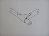
I don't know the dimensions of your arm. I was just drawing arms with dimensions from something I did earlier just as an example.

If your going to misalign the rear inner rod end then you might as well do the front inner by the same amount because it straightens your load path.

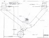
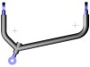
" Below is the version I plan on using unless someone does not agree."

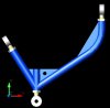
If the outer rod end axis is not exactly transverse then when you set camber with it it's going to change caster at the same time, this necessitates correcting the caster with the inner rods ends which in turn affect camber. It isn't impossible but is problematic. That's why I angled the last arm drawing to show that the outer rod end was transverse. The advantage of your design is simpler construction and one less piece.

You still need to move the front leg connection at the outer rod end out until it's at the jam nut surface. It will give you more shock clearance and straighten the load path. Angling the front rod end as much as possible will do this also. Imagine 2 lines running from dead center of the outer rod end ball to the center of each inner rod end ball. This is the optimum straight load path. You want to get as close to that as possible with the clearance you have.

""Also I talked with my machinist/welder and he states that if you use self-annealing welding wire (which is not hard) you do not need to normalize after welding. This is what all chassis builders use when welding 4130. If you normalize a complete chassis you could end up with everything way out of whack since it also relieves any tension created during the welding process.""

I've argued back and forth and have been on both sides of the normalization issue. I've finally ended up thinking you need normalization to realize the benefits of 4130, without it you may be worse off than mild steel. Self annealing wire won't normalize the HAZ other than the deposited material.

Current technology has taken care of this issue, it's a machine called www.meta-lax.com and it works without warpage. Maybe there's a welder close by that has it. Suspension arms aren't something you want to be brittle.
 
Kalun,

Draw a line between the center line (mounting holes) of the two rod ends that attach to the frame. This is the line that the mounting bolts go through. Now take the angle from the bolt line and the angle of the rod end. As you have it, it won't work. A normal rod end will only twist left and right 10%. A high miss rod will twist 19%. The angle at which your rod ends twist in relation to the line through the centers is like 30 or so degrees. Just an observation. I would like to thank you and Trevor for all your help.
 

Chris Duncan

Supporter
I understand what you're saying Richard, my drawings are just representations and not dimensionally accurate for any particular aplication. You could put the front rod end at the same angle as the rear to optimize your design, that's all I was trying to represent.
 
Hi guys,

Question:

I'm working on my front suspension too (It's a GTD).
I'm replcing the suspensionbushes with polyurethane bushes.
Since I'm also changing the brackets which hold the suspension arms, I want to change the upperwarm with Uniballs. I was wondering, how about the bushes then? Because it won't be possible the use bushes in that way??? Is that okey??? if it has only bushes for the bottom arm, and not the upper, would that be okey ??? Thanx
 
Back
Top