
yes ,I plan to use the OBD2 for the AIM unit . I need the tach signal for a pump controller and a controller so that I don't over rev the a/c compressor. both need an independent tach signalHey Hector, aren't you going to be using the AIM dash? If so, you just pick up tach with the OBD2 channel. If you do still need a separate output, tyen yes you can use the Bulkhead connector, position L wire. I used that with the KOSO gauge before I changed to my AIM. You may need a pullup resistor depending on your use.

You are using an out of date browser. It may not display this or other websites correctly.
You should upgrade or use an alternative browser.
You should upgrade or use an alternative browser.
Restarting my SLC project in West Texas
- Thread starter felizguy
- Start date
Ken Roberts
Supporter
I would have just used the OEM location for the forward oxygen sensors on your cast LS3 manifolds. I can confirm that was where they were originally intended to be installed. Over the years GM kept moving them closer and closer to the engine. They are possibly easier to access too.O2 sensor and oil pressure sensor questions for an LS3 525 crate motor.
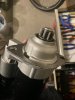
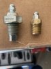
Ok guys, I am stuck a bit on the oxygen sensors and oil pressure sensor, I read not to put the oxygen sensors facing up and about 6-7 inches after exhaust comes together from all 4 cilinders on each side, I am not installing an oil cooler YET. So I got the oil adapter plate Alan suggested that has 3 1/8 NPT holes ,
Questions: Is that location of the oxygen sensors OK? should I have just used the hole on the exhaust manifold (it is right in the middle, technically where the exhaust comes together, so which one should I plug? and what plug and gasket I(f any) should I use (pretty hot in there).
Is it OK to use an adapter from the oxygen sensor thread to an 1/8 NPT thread so that I can plug it into the oil adapter plate? Will the extra space caused by the adapter and the smaller hole mess up the oil pressure reading?
Thank you very much
Thanks Ken, good to know, on all the forums people recommend the optimal location being 6-7 inches downstream on the down pipe and that is why I welded the plugs at that location, I guess I now have the advantage of 2 different locations and see if there are any differences in the readings. Good research project!!! My guess is you are probably right , however sometimes decisions get made for manufacturing and accessibility reasons with a slight compromise in accuracy, We shall see .I would have just used the OEM location for the forward oxygen sensors on your cast LS3 manifolds. I can confirm that was where they were originally intended to be installed. Over the years GM kept moving them closer and closer to the engine. They are possibly easier to access too.
My guess is the the air will be more mixed and therefore will yield more consistent readings and less variation at the downstream location but its is pure speculation on my part. Also I assume there will be significant differences in turbulent vs laminar flow as you go downstream. Again, pure assumption. I have to learn a lot about ECUs and tuning. First I need to fire the beast, it is taking long enough LOL.
Ken Roberts
Supporter
If you look closely at the flow path (especially with the cast LS3 exhaust manifolds) you can see that all four cylinders exhaust flow converge at the center portion where the sensor tip is located. The sensors work their best in the hottest part of the exhaust. OEM engineers spend a lot of time in research and development. I’m sure you will be fine with either location.
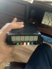
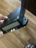
Quick question for you , I know Scott went through this question a few years back, but I could not find the exact solution. What is the easiest way to install a front wheel speed sensor, I have the standard suspension and front hubs and rotors, I am using the Graziano unused front wheel shaft as my engine speed sensor and I need a front wheel speed (which provides the actual vehicle speed signal to the traction control unit). My son Miguel helped me clean up the racetronics controller with a new 3d printed case and new button circuitry instead of the removable faceplate and will mount directly to the dashboard , the only thing I am missing now is the front wheel speed sensor location. It is an M8 1.0 thread sensor and needs to be 0.062 inches or less from a metal surface.
Thanks for your help.
Thanks for your help.
Attachments
Well, it has been exactly one year to the day since my last post . Amazing how quickly time flies. So, like Carroll Shelby says, like my cars, I will make this fast. Had another cancer scare, another surgery, more treatments , but now feeling great, healthy and got one more month before I finish everything, and enough of that. Quite a bit of work done so I will post one major job at a time in case anybody has questions or comments it will make it a bit easier. And here it goes:
Hector, glad to hear things are turning around for you. Will certainly welcome your updates. Stay well, and be safe.
Regards Brian
Regards Brian
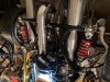
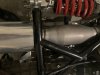
After dealing with a cat less exhaust and a very loud muffler on my previous car , I decided to tone it down a bit . Went with the quietest and shortest option I could find. I settled with the Flowmaster DBX FLO-13014310 , and the hi flow racing cat 200 cell XFO-S0004 both from Summit Racing .
I had them all coated by Jet Hot , I believe in Oklahoma??? It was a lot cheaper to send components individually and the downpipes got internal coating as well that is why the welds are not coated. I welded the components locally at a local muffler shop.
I wish I would have used shorter and thinner Cats, they give minimal space for the shifter cables, I had to create micro louver shields and insulate the crap out of them, so far so good.
Attachments
Last edited:
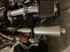
So also did the intake, initially the bend was too steep and the filter was hitting the transmission, I shortened the intake and changed the angle All is well, the intake sits nicely on the black support frame
Attachments

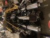
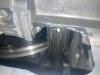
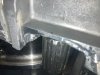
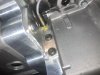
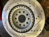
Well, I remembered that one had to grind a bit to accommodate the front wheel drive shaft from the Graziano, so I thought why not use the shaft teeth as a counter for my traction control system . Since I had to make a closeout plate anyway I attached a sensor that would be triggered by the teeth. , well , nice try but the teeth are not wide or deep enough to trigger the sensor . I have not solved the problem of finding an rpm source for the traction control unit to compare it to front wheel speed and sense wheel spin . Next step is the transmission speed sensor , not sure if it will work , but I have it wired all the way to the traction control unit
Attachments
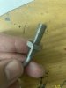
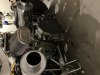
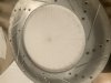
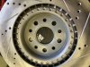
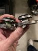
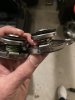
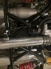
And since my last post from a year ago was about front wheel sensors , here is my solution that will meet the criteria for the sensor as well as a large number of triggers per revolution which will help with sensitivity at low speeds . I plan to use 2 sensors, one for the traction control unit and another for the AIM MXS Strada Dash speed source.
This was the solution suggested by John Gregory that designed the traction control unit .
This was the solution suggested by John Gregory that designed the traction control unit .
Attachments
Thank you Brian, I appreciate it.Hector, glad to hear things are turning around for you. Will certainly welcome your updates. Stay well, and be safe.
Regards Brian
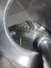
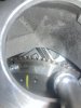
Well.most people push the start button and everything runs great. Not me. I push the starter and as the engine starts running I hear this horrible metal grinding noise, holly crap I blew the engine up . Luckily my friend super Dave was around to help me diagnose the noise. The starter gear was not clearing the flywheel. Easy solution, a hand made shim. And noise went away. Happy when is that easy , hardly ever.
I am curious to hear how many people had the same problem? I have not heard of a single one so far. Lucky me I guess.
I am curious to hear how many people had the same problem? I have not heard of a single one so far. Lucky me I guess.
Attachments
OK time to bleed the clutch, the bleed screw that came with the kit is a cheap substitution and does not work . fluid leaked everywhere, it was a mess. needs an O ring. That is sooo annoying . And in the middle of the COVID disruption it took forever to find the part in Europe , had it shipped from England , non of the US Audi dealerships had it , and the one that did never sent me the part . Long painful story .
Did anybody go through this? I even called RCR and the pointed me to the wrong part number that comes with the kit. Very very frustrating !! This kind of crap should not happen, period!!! It is not rocket science and basic decency and customer service. C'mon Fran !!!
Did anybody go through this? I even called RCR and the pointed me to the wrong part number that comes with the kit. Very very frustrating !! This kind of crap should not happen, period!!! It is not rocket science and basic decency and customer service. C'mon Fran !!!
Attachments
Ok fired up the engine and runs like crap!! Long story short I plugged the crank sensor wire into the oil temp and level sensor (yes, same size plug and the plugs are close to each other (don't ask how can that possibly happen? ) And I am confused why the crate engine harness does not have a connection to the oil temp and level sensor? that makes no sense to me .

 www.youtube.com
First Start
www.youtube.com
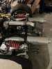
OK here comes the fun part . The driver side catalytic converter got glowing red hot, I mean really really hot . The engine is running like crap, something is going on. It took a while to figure it out . Did engine diagnostics and figured out that I had plugged the crank position sensor in the wrong plug . Dumb , Dumb, Dumb, OK plugged it correctly, engine runs great and cat starts glowing again, the coating craps out and turns dull . Engine overheats over 230, water starts boiling . Whats up now?
First problem, the radiator overflow tank , bought in on eBay, probably Chinese made , the flange is manufactured wrong, not thick enough , the cap does not create a seal, therefore air enters the system . Took a while to figure out
Fix: bend tabs on the cap (I can get creative sometimes ) and voila , problem fixed . Tank sealed, system bleeds itself (Thank you very much Howard )
Why does this crap happen to me ? badly manufactured overflow aluminum tank , seriously? Then I remembered I had to re tap the threads on the same freaking tank , it was not fully threaded .
Well, I will probably have to replace it , but everything is working well,
Cat is still getting super hot . entire outside surface glowing bright red in only a couple of minutes. Fuel problem? a bunch of fuel got dumped when the crank sensor was connected the wrong way? , coil problem? This one took a while to solve. So I created a new post to explain the details .
The cat needs to be replaced, (it looks like crap ) but the problem is not solved yet
Attachments
Similar threads
- Replies
- 19
- Views
- 3K
- Replies
- 8
- Views
- 1K
- Replies
- 16
- Views
- 7K