Picture Request: Fuel Pump Arrangement

Andrew

Supporter
Evening chaps,

As per the title. I'm looking at redoing the layout of my fuel pumps / sight bowls and would like to see what other have done for some much needed inspiration!

Current arrangement
Sequence 01.Still001.jpg
 

Neil

Supporter
Are glass bowl fuel filters legal? If one breaks there will be gas sprayed all over your engine compartment.
 

Howard Jones

Supporter
I would mount the entire assembly on a single plate and then mount the plate on the bulkhead so it can be removed as one after disconnecting the necessary AN lines. You obviously are aware of the fuel line within inches of the headers. Maybe use with a single large filter with replaceable element canister, then pumps, and finally the pressure regulator.

I would eliminate as much braided line as possible and use solid tubing on the assembly plate. It never is affected by the fuel and will last forever.
 
Sems you have a twin pump diagram ... that's ok but why do you have 2 regulators ?
Are they both connected to the engine ?
Do you have check valves at every pump out let ?
To minimise hoses , leaks etc you can also use a small "low pressure" welded tank to connect pumps flow with inline filters , from there going to one regulator and then to the engine
 

Andrew

Supporter
To be honest, its how the car came (I bought a built car) so I'm getting my head around what's been installed & why :)
 

Andrew

Supporter
I would mount the entire assembly on a single plate and then mount the plate on the bulkhead so it can be removed as one after disconnecting the necessary AN lines. You obviously are aware of the fuel line within inches of the headers. Maybe use with a single large filter with replaceable element canister, then pumps, and finally the pressure regulator.

I would eliminate as much braided line as possible and use solid tubing on the assembly plate. It never is affected by the fuel and will last forever.

Thanks Howard, that sounds like an avenue to explore! Do you have any examples of the bulkhead mounted plate by chance?
 
You can have some interesting info here ; https://www.gt40s.com/threads/keith-bakers-southern-gt-on-the-build.34367/page-8
Look from post 158

There are so many arrangement possible ; depending on how yo want to upgrade your system
do you want only to minimise hoses keeping all ancilaries ?
Do you want to go to a new circuit ? keepeng all ancilaries but locating those better ?
Do you know how are done picking points on your fuel tanks

I have most of accessories done in cad and can help you friendly to install those virtualy so you can look better at what you can improve ;) ;)
Up to you ....
 

Attachments

  • Pompe facett.JPG
    Pompe facett.JPG
    82.2 KB · Views: 251
  • tube liaison filtre asp pompe Bosch.JPG
    tube liaison filtre asp pompe Bosch.JPG
    59.4 KB · Views: 301
  • fuel circuit.JPG
    fuel circuit.JPG
    149.5 KB · Views: 260
2017-06-13 10.57.55.jpg

Hi Andrew,

Attached is picture of my set up, these are two Mitsuba pumps, they load the swirl tank depending which side you are using, then the high pressure pump pulls to to the injectors via a filter. Any return goes back to the swirl tank and then depending what solenoid is open to the tank in use. No glass bowls in sight. Hope this helps.

Don
 
Thanks Howard, that sounds like an avenue to explore! Do you have any examples of the bulkhead mounted plate by chance?
Seems like you could get a 12x12 sheet of 3/16" aluminum, which would allow you to tap directly into it, rather than using nut certs. Then sink a couple rivnuts into the chassis in appropriate locations to fasten the plate to the chassis. Rigid lines with 2 90 degree bends to allow disassembly between components, or Teflon lines between components on the plate, and teflon lines from the plate to the surge tank & regulator.
I had standard earl's lines for all my fuel plumbing. Was advised by a vendor to replace all of it with teflon due to methanol and gas additives. When I pulled out the old lines, they were rigid, had stinky, brown liquid inside them.
 
I wanted to have a less-cluttered firewall in the engine bay.

DSC09929.JPG


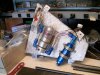
Therefore, I opted to putting all of my fuel system in a cavity in the engine bay.

Fuel pumps 003.JPG


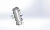
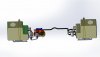
At the top of the picture in the cavity, you will see two rectangular tees that I made, one for supply, one for return. I built these to have an internal volume to reduce the velocity in the tee rather than using a traditional tee. On the right side of the cavity is the low-pressure fuel pump that draws from both tanks through the tee and then supplies the swirl tank located at the back of the cavity (bottom of picture). Out of the swirl tank, I go through a 100 micron filter to the high-pressure pump and then to a 10 micron filter to the pressure regulator. The return from the fuel rail goes back into the swirl tank, and the overflow from the swirl tank goes to the tee and then to each fuel tank.

I do have a little problem in that the return fuel would prefer to go to the right tank, so that tank increases in level a little bit as I drive. I need to put a valve on it to help balance the flow.

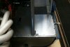
As shown in the first photo, a cover goes over all of the fuel system. The polished aluminum plate covers my tool box. I would say that I could carry a 6-pack in my "storage trunk", but it is already full of an air pump and tools.

Now, before you observant folks say something, I am in the process of redoing the rear suspension, so the car is taken apart a bit.

-Bob Woods
Tornado GT40 in Texas
 

Attachments

  • Fuel pumps 005.JPG
    Fuel pumps 005.JPG
    238.3 KB · Views: 311
Back
Top