Howard Jones
Supporter
I have started this thread in an effort to make available all I have learned about this subject in an easily searchable place. Of course, I don't propose that I know it all or that everything to be known is in this original post but I think that a central location for this subject with a simple search title will be useful to many. So here it goes.
I have a Davies Craig EWP 150 with a DC controller installed in my SLC. I have run this pump since the first time I started up the car apon completing the initial build. The engine in the car is a SBC making 430ish HP at the flywheel. At first, I used the standard RCR radiator and the as-delivered fans that RCR included in the kit. More on this later.
I learned how to efficiently bleed a V8 in a mid-engined car when I built and developed my GTD40 so on this car I installed bleed ports at the rear of both heads. "T'ed" them together and connected the single line (all AN-4) to the expansion tank. I also ran a separate line from the front of the car back to the same expansion tank. At the radiator, I used the two ports at the top of the radiator on each side to again "T" them together and connect them to the single line going back to the rear of the car. So the bleed system ties all the highest points in the car together at the expansion tank.
The expansion tank MUST be located at the highest point available in the car. This is a very important point. The expansion tank connection to the cooling system (expansion line) MUST be connected to the lowest PRESSURE point in the system. This will always be at the pump inlet return from the radiator right before and as close to the low-pressure side of the impeller as possible. This will also be the lowest-temperature coolant in the system. This is also a very important point.
Pump location: the pump should be placed so that the highest pressure available is directly applied to the hottest heat-generating point in the system, This will always be the ports that the previously removed mechanical pump used to deliver cool water to the engine. Engine design is different from engine to engine but in any case as close to the engine cool inlet as possible. The pump inlet position should be as low in the car as possible to place as much of the total water volume as possible ABOVE the pump. This is known as "head". Think of a damn and its electrical generation turbines. The turbine inlets are always BELOW the dam for just this reason.
Head is the biggest problem to overcome in a mid-engined car. Especially a very low car with the water volume also physically very low. And this is the first real reason to use an electric pump. The pump in comparison to a traditionally located mechanical pump can be placed much lower thus improving head. In both a SBC and SBF with a mechanical pump, MOST of the water volume is below the pump inlet. The radiator volume is lower, as well as the transfer pipes and nearly all the water in the engine with the exception of the water in the heads. This is exactly wrong and why an electric pump must be located as low as possible.
The second reason is that a mechanical pump is driven as some derivative of engine speed. Its impeller is always either running too fast or too slow in a road race application. Here the rev range of the engine works against the efficiency curve of the impeller. The engine rev range is far wider than the effective impeller rev range. Fluid pump impellers typically don't like to be driven faster than about 3000-3500 rpm and need about 1000-2000 rpms to enter into the linear and most efficient portion of their performance curve. This can be addressed in a street car with pulley ratios where engine speed is usually just off idle and nearly always below 3000-3500 rpms. Just select a pulley ratio that keeps the impeller speed at 1500-3000 rpms and all is well. But if you spin it too fast, you get cavitation. Too slow and it's not really efficient. However, in a street engine power levels and thus heat generation are usually pretty moderate and you can get away with it. After all our V8s are making far less than 50hp at idle and usually less than 100hp at cruise speed. This is a lot less heat load.
Run the engine on track at 60-100% of its maximum power and use a rev range of 2800-6600 rpms for a 1/2 hour continually and it just will not work. Especially no matter what pulley ratio you select the impeller is faced with a 4000 rpm use band and it spends too much time out of its best efficiency range. An electric pump solves ALL this by running a set speed that is calculated to turn the impeller at exactly its most efficient rpm. On/off duty cycle is used to accommodate changes in heat load. This is exactly what the control box is doing on a DC system.
Note: I tried to locate my pump up at the front of the car for packaging reasons. It did work there but it DID work better in the rear of the car attached directly to the engine. I suspect pressure loss over the pipe distances was the reason. Remember a mid-engined car has an effective coolant system length that is many times longer than a front-engined car. A point to remember is every 90-degree turn in fluid flow is an effective 3-foot increase in system total length for a 1/12-inch diameter pipe. Our mid-engined cars have an effective coolant path length of at least 30 feet. In reality, it is quite a bit more than that.
So an electric pump has huge advantages. But are they reliable? I say yes. The market has driven the development of EWP to the point that there isn't much concern with reliability with modern designs. Many OEM's are using them in production cars with no real ill effect on warranty costs.
So do I use one with a mechanical pump? You can....... but I would recommend that you bin the mechanical pump and design the system correctly on the first go.
Do I keep the thermostat? Not on a DC system, The controller is the thermostat. Other pumps recommend you use the thermostat to control system temp because their pump is only a pump. That's not bad it's just the way their system is designed to work. Install the pump using the manufactures instructions and you will be fine.
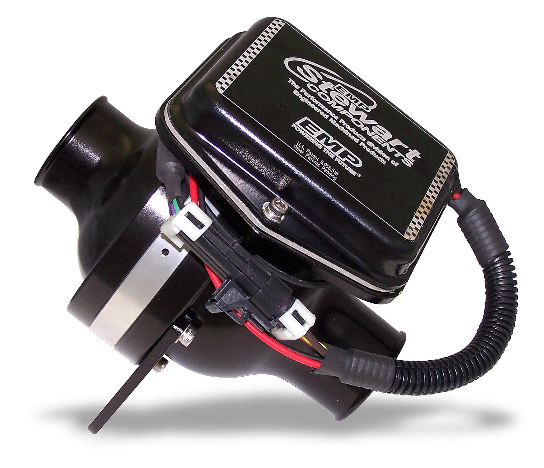
Who makes good pumps? Davies Craig, Stewart, and Meziere are all good. There are also OEM pumps that would work as well I suppose. I haven't looked into them as thoroughly.
OH....Drag race setup with the EWP simply replacing the Mech pump. In a word, No. It negates all of the placement advantages discussed above. Because of the length of the system AND the Head issue don't use one of those in a mid-engined car.
Pitfalls: Place the sensor for the controller at the top of the intake manifold where the coolant is hottest. This is also very important
Very high HP: When I was talking to an engineer at Stewart Racing pumps, he described how EWP's are used in LeMans Prototypes. They use two pumps. One at the engine coolant inlet as I describe above and a second one at the radiator hot side inlet. This effectively divides the total system length into two parts allowing pressure to remain higher throughout the system and thus flow rates. It also provides for a redundant system in the event of a single pump failure.
So how does it work for me? I have run my SLC at COTA on days when the temperatures were too hot for me to continue to drive the car in the afternoon session. I seriously believed I was doing something that might be dangerous. I'm taking air temps in the sun of 106F and humidity levels above 80%. THATS FUCKING HOT! The car ran solidly at 191F all day exactly on the controller's default setting. I have no doubt that if I had set it to 180 or 185 it would have been just fine.
Another important point for track cars. OIL COOLERS!!!!! You need to control oil temps just like you control coolant temps. Oil temps should be held above 225F and below 275F. Install a cooler that will achieve that temperature range on a day as I describe. Oil system capacity: you need at least 7-8 quarts systems, Less than that and it gets hard to cool the oil for 30 mins with 400-500HP on a 105F day.
Remember the air temps the cars see are about 4-10 inches off the asphalt. I have aimed a laser temp gauge at the track and seen track temps above 150F on more than one occasion. IN MID MORNING! God only knows how hot the track is at 4pm in Texas in August....................... That is what is going into the radiators.
Radiators: I bought a custom-built C&R radiator for my SLC early on in this process. I am sure it works very well. However, I am not convinced that if I had run the RCR standard radiator it would not have worked well also. Do everything else right first before you buy a new $1200 radiator and huge fans, By the way, I am still running the RCR standard fans. They work fine for cooling the car as I leave the track and drive slowly back to my pit location.
Fans: You can overcome a badly designed ducting system (nor none at all) by installing huge fans, What is happening is you make the radiator believe it is going 60-70mph through the air all the time with the fan airflow. If you need to run the fans at highway speed to cool the car you need to work on ducting. There is no reason to run the fans at 65mph at cruise IF you have a good ducting system. After all the engine only makes 50 -80 Hp at part throttle when you are cursing along at 70mph or so. There is plenty of airflow volume at the nose inlet to cool that. BUT it needs to be forced to flow THROUGH the radiator and out of the bodywork.
Last thing: Ducting! Every effort needs to be made to ensure ALL the air going into the front of the car is forced to go through the radiator and then forced to leave the bodywork out of the top of the car. This may be the single cheapest way to make the coolant system work well after an effective bleed system.
Oh, and ducting will solve all of your hot interior footbox problems at the same time.
Be cool buddies!
I have a Davies Craig EWP 150 with a DC controller installed in my SLC. I have run this pump since the first time I started up the car apon completing the initial build. The engine in the car is a SBC making 430ish HP at the flywheel. At first, I used the standard RCR radiator and the as-delivered fans that RCR included in the kit. More on this later.
I learned how to efficiently bleed a V8 in a mid-engined car when I built and developed my GTD40 so on this car I installed bleed ports at the rear of both heads. "T'ed" them together and connected the single line (all AN-4) to the expansion tank. I also ran a separate line from the front of the car back to the same expansion tank. At the radiator, I used the two ports at the top of the radiator on each side to again "T" them together and connect them to the single line going back to the rear of the car. So the bleed system ties all the highest points in the car together at the expansion tank.
The expansion tank MUST be located at the highest point available in the car. This is a very important point. The expansion tank connection to the cooling system (expansion line) MUST be connected to the lowest PRESSURE point in the system. This will always be at the pump inlet return from the radiator right before and as close to the low-pressure side of the impeller as possible. This will also be the lowest-temperature coolant in the system. This is also a very important point.
Pump location: the pump should be placed so that the highest pressure available is directly applied to the hottest heat-generating point in the system, This will always be the ports that the previously removed mechanical pump used to deliver cool water to the engine. Engine design is different from engine to engine but in any case as close to the engine cool inlet as possible. The pump inlet position should be as low in the car as possible to place as much of the total water volume as possible ABOVE the pump. This is known as "head". Think of a damn and its electrical generation turbines. The turbine inlets are always BELOW the dam for just this reason.
Head is the biggest problem to overcome in a mid-engined car. Especially a very low car with the water volume also physically very low. And this is the first real reason to use an electric pump. The pump in comparison to a traditionally located mechanical pump can be placed much lower thus improving head. In both a SBC and SBF with a mechanical pump, MOST of the water volume is below the pump inlet. The radiator volume is lower, as well as the transfer pipes and nearly all the water in the engine with the exception of the water in the heads. This is exactly wrong and why an electric pump must be located as low as possible.
The second reason is that a mechanical pump is driven as some derivative of engine speed. Its impeller is always either running too fast or too slow in a road race application. Here the rev range of the engine works against the efficiency curve of the impeller. The engine rev range is far wider than the effective impeller rev range. Fluid pump impellers typically don't like to be driven faster than about 3000-3500 rpm and need about 1000-2000 rpms to enter into the linear and most efficient portion of their performance curve. This can be addressed in a street car with pulley ratios where engine speed is usually just off idle and nearly always below 3000-3500 rpms. Just select a pulley ratio that keeps the impeller speed at 1500-3000 rpms and all is well. But if you spin it too fast, you get cavitation. Too slow and it's not really efficient. However, in a street engine power levels and thus heat generation are usually pretty moderate and you can get away with it. After all our V8s are making far less than 50hp at idle and usually less than 100hp at cruise speed. This is a lot less heat load.
Run the engine on track at 60-100% of its maximum power and use a rev range of 2800-6600 rpms for a 1/2 hour continually and it just will not work. Especially no matter what pulley ratio you select the impeller is faced with a 4000 rpm use band and it spends too much time out of its best efficiency range. An electric pump solves ALL this by running a set speed that is calculated to turn the impeller at exactly its most efficient rpm. On/off duty cycle is used to accommodate changes in heat load. This is exactly what the control box is doing on a DC system.
Note: I tried to locate my pump up at the front of the car for packaging reasons. It did work there but it DID work better in the rear of the car attached directly to the engine. I suspect pressure loss over the pipe distances was the reason. Remember a mid-engined car has an effective coolant system length that is many times longer than a front-engined car. A point to remember is every 90-degree turn in fluid flow is an effective 3-foot increase in system total length for a 1/12-inch diameter pipe. Our mid-engined cars have an effective coolant path length of at least 30 feet. In reality, it is quite a bit more than that.
So an electric pump has huge advantages. But are they reliable? I say yes. The market has driven the development of EWP to the point that there isn't much concern with reliability with modern designs. Many OEM's are using them in production cars with no real ill effect on warranty costs.
So do I use one with a mechanical pump? You can....... but I would recommend that you bin the mechanical pump and design the system correctly on the first go.
Do I keep the thermostat? Not on a DC system, The controller is the thermostat. Other pumps recommend you use the thermostat to control system temp because their pump is only a pump. That's not bad it's just the way their system is designed to work. Install the pump using the manufactures instructions and you will be fine.
Who makes good pumps? Davies Craig, Stewart, and Meziere are all good. There are also OEM pumps that would work as well I suppose. I haven't looked into them as thoroughly.
OH....Drag race setup with the EWP simply replacing the Mech pump. In a word, No. It negates all of the placement advantages discussed above. Because of the length of the system AND the Head issue don't use one of those in a mid-engined car.
Pitfalls: Place the sensor for the controller at the top of the intake manifold where the coolant is hottest. This is also very important
Very high HP: When I was talking to an engineer at Stewart Racing pumps, he described how EWP's are used in LeMans Prototypes. They use two pumps. One at the engine coolant inlet as I describe above and a second one at the radiator hot side inlet. This effectively divides the total system length into two parts allowing pressure to remain higher throughout the system and thus flow rates. It also provides for a redundant system in the event of a single pump failure.
So how does it work for me? I have run my SLC at COTA on days when the temperatures were too hot for me to continue to drive the car in the afternoon session. I seriously believed I was doing something that might be dangerous. I'm taking air temps in the sun of 106F and humidity levels above 80%. THATS FUCKING HOT! The car ran solidly at 191F all day exactly on the controller's default setting. I have no doubt that if I had set it to 180 or 185 it would have been just fine.
Another important point for track cars. OIL COOLERS!!!!! You need to control oil temps just like you control coolant temps. Oil temps should be held above 225F and below 275F. Install a cooler that will achieve that temperature range on a day as I describe. Oil system capacity: you need at least 7-8 quarts systems, Less than that and it gets hard to cool the oil for 30 mins with 400-500HP on a 105F day.
Remember the air temps the cars see are about 4-10 inches off the asphalt. I have aimed a laser temp gauge at the track and seen track temps above 150F on more than one occasion. IN MID MORNING! God only knows how hot the track is at 4pm in Texas in August....................... That is what is going into the radiators.
Radiators: I bought a custom-built C&R radiator for my SLC early on in this process. I am sure it works very well. However, I am not convinced that if I had run the RCR standard radiator it would not have worked well also. Do everything else right first before you buy a new $1200 radiator and huge fans, By the way, I am still running the RCR standard fans. They work fine for cooling the car as I leave the track and drive slowly back to my pit location.
Fans: You can overcome a badly designed ducting system (nor none at all) by installing huge fans, What is happening is you make the radiator believe it is going 60-70mph through the air all the time with the fan airflow. If you need to run the fans at highway speed to cool the car you need to work on ducting. There is no reason to run the fans at 65mph at cruise IF you have a good ducting system. After all the engine only makes 50 -80 Hp at part throttle when you are cursing along at 70mph or so. There is plenty of airflow volume at the nose inlet to cool that. BUT it needs to be forced to flow THROUGH the radiator and out of the bodywork.
Last thing: Ducting! Every effort needs to be made to ensure ALL the air going into the front of the car is forced to go through the radiator and then forced to leave the bodywork out of the top of the car. This may be the single cheapest way to make the coolant system work well after an effective bleed system.
Oh, and ducting will solve all of your hot interior footbox problems at the same time.
Be cool buddies!
Last edited: