On my RCR with the +2 suspension I found that the rear suspension droop is being limited by the drive axle angle rather than the shocks. I undo the drive axles and it drops to the shock extension, way below where the axle could hook up. Looks like I'll have to get some shorter shocks. Wondered how many others have found this same problem.

You are using an out of date browser. It may not display this or other websites correctly.
You should upgrade or use an alternative browser.
You should upgrade or use an alternative browser.
RCR rear suspension limited by drive axle angle
- Thread starter Paul Thon
- Start date
Jim Albright
Supporter
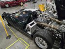
Your setup looks about similar to what I'm going to have to do with the one I'm working on. Have an RCR MkI that's getting a Godzilla and 7MT Porsche 7spd manual in it. Did you have any issues after flipping the bracket for the rear pan? The 7MT is stupid wide and after scanning and checking everything in CAD, I have to either lower the whole assembly more, or move the upper control arm mounting point more outboard.I had to install limiting straps, as the first time I jacked up the car, the CV boot flange was damaged by the droop. LS7 with Graziano transaxle.
Jim Albright
Supporter
Tim,
Not sure what bracket you are referring to - my chassis was assembled by RCR, and I originally was assured I could run the original tire sizes with the RCR chassis. After installing the transaxle, there were issues with the passenger side axle angle that forced me to have to settle for much narrower rear tires. I see you are only 240 miles away, so if you want to stop by and look at my configuration you are more than welcome.
Best Regards,
Jim
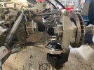
This one here. On our kit, it came with the bracket mounted in this configuration:Tim,
Not sure what bracket you are referring to - my chassis was assembled by RCR, and I originally was assured I could run the original tire sizes with the RCR chassis. After installing the transaxle, there were issues with the passenger side axle angle that forced me to have to settle for much narrower rear tires. I see you are only 240 miles away, so if you want to stop by and look at my configuration you are more than welcome.
Best Regards,
Jim
And here's where I was fitting everything together and noticed the interference...
Jim Albright
Supporter
I see what you mean - the pan support rod positions on yours are the transaxle support rods on mine and the separate tail support rods are further outboard and use a separate bracket off the upper control rod bolt. Pic attached.
Attachments
Randy Folsom
Supporter
Paul,
Thanks for opening this discussion. I had not thought to check what was limiting the rear droop with the axles in place.
The rear droop on my car is limited by the lower four link rod at the chassis opening. I have not checked to see if the axle will further limit the droop before the rod hits the chassis. In either case, I will fold a thick piece of thick rubber over the opening and bolt in place to limit the travel to just above the axle limited droop.
The bracket provided by RCR to fasten the rod end that supports the rear clam is designed for easy manufacture, but is not ideal for providing clearance for the axle shafts. I made brackets from a short length of 2" x 2" x 1/8" steel angle stock much like Jean-Marc's picture. I also made smaller diameter rods and used the smaller rod ends on both ends.
Nice! that's an idea that I may seriously have to entertain. My initial thought was just to rotate the bracket to where the flat flange is up, which will help on the room, but it will be close. The current situation I found myself in is realizing that the lower control arms (this kit was purchased second hand unfortunately) have been shortened. They used to be the +2 LCAs, but they had an inch hacked off of each end. I redesigned and 3d printed a test piece just to check fitment, and when I go to connect the lower 4 link arm, the chassis prevents it from moving outboard enough, even with it having been clearanced previously. The chassis was set up for a coyote engine, so the upper 4 link mounts were moved outboard, and so the lowers have as well. I'm not sure I see how it will have enough angle to attach and move correctly...Paul,
Thanks for opening this discussion. I had not thought to check what was limiting the rear droop with the axles in place.
The rear droop on my car is limited by the lower four link rod at the chassis opening. I have not checked to see if the axle will further limit the droop before the rod hits the chassis. In either case, I will fold a thick piece of thick rubber over the opening and bolt in place to limit the travel to just above the axle limited droop.
The bracket provided by RCR to fasten the rod end that supports the rear clam is designed for easy manufacture, but is not ideal for providing clearance for the axle shafts. I made brackets from a short length of 2" x 2" x 1/8" steel angle stock much like Jean-Marc's picture. I also made smaller diameter rods and used the smaller rod ends on both ends.
View attachment 151366
Also, can anyone give me the length of the upper control arm that coincides with the +2 kit?
My upper link measures 11 inches center to center on the bolts. Upper 4 link arm is 32 1/2 inches.Nice! that's an idea that I may seriously have to entertain. My initial thought was just to rotate the bracket to where the flat flange is up, which will help on the room, but it will be close. The current situation I found myself in is realizing that the lower control arms (this kit was purchased second hand unfortunately) have been shortened. They used to be the +2 LCAs, but they had an inch hacked off of each end. I redesigned and 3d printed a test piece just to check fitment, and when I go to connect the lower 4 link arm, the chassis prevents it from moving outboard enough, even with it having been clearanced previously. The chassis was set up for a coyote engine, so the upper 4 link mounts were moved outboard, and so the lowers have as well. I'm not sure I see how it will have enough angle to attach and move correctly...
Also, can anyone give me the length of the upper control arm that coincides with the +2 kit?
Thanks a bunch! If at all possible, whenever it's convenient, do you think you could get me the barrel length? Currently the uppers on my kit have a barrel length of 7in and center to center of the bolts is about 9 5/8in, however the heims are pretty much run all the way in...My upper link measures 11 inches center to center on the bolts. Upper 4 link arm is 32 1/2 inches.
Barrel lenght is 8 inches.Thanks a bunch! If at all possible, whenever it's convenient, do you think you could get me the barrel length? Currently the uppers on my kit have a barrel length of 7in and center to center of the bolts is about 9 5/8in, however the heims are pretty much run all the way in...
Very much appreciated sir, thank you!Barrel lenght is 8 inches.
Hey Jim, I was wondering if you could contact me on here? I may need to take you up on the offer to come check out your GT40 to try and cross reference a few things and get some clarity..Tim,
Not sure what bracket you are referring to - my chassis was assembled by RCR, and I originally was assured I could run the original tire sizes with the RCR chassis. After installing the transaxle, there were issues with the passenger side axle angle that forced me to have to settle for much narrower rear tires. I see you are only 240 miles away, so if you want to stop by and look at my configuration you are more than welcome.
Best Regards,
Jim
Similar threads
- Replies
- 18
- Views
- 7K