John -
First off - thank you for the information on the Toyota parts - actually, I just purchased a Toyota idler pulley replacement for the hydraulic pump fan drive from David (Lextreme) off of eBay.
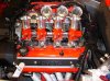
Secondly, please forgive my lack of engine knowledge but I have a few questions about the changes you are making to your engine. Why are you converting to a crank triggered ignition system? Are there specific advantages to going this route? The twin distributors appear bulky and overly complicated to a novice like me - just wondering if they create other problems with tuning. If you eliminate the distributors, are you able to use the stock cam pulleys? Another basic question probably but are there advantages to using individual COP's rather than using the 2 coil packs? Finally, does the 36-1 tooth trigger wheel simply replace the 12 tooth trigger wheel for the fuel injection?
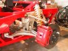
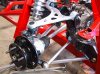
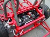
I spent today removing all of the external components of the engine - wiring harness, alternator, PS, hydraulic pump fan drive, AC compressor, intake, etc. I was amazed at how heavy the full engine wiring harness is! I'm now contemplating tearing the engine down to see how things look inside - I found what appeared to be a squirrel's nest under the intake. Hopefully that's not an indicator of the condition of the internals!
Regards,
Dave L
Dave, concerning the crank triggered ignition and COP's, there are multiple benefits:
1) A crankshaft reference can provide a much more accurate and stable indication of where a piston is in the cylinder than the distributor can. And an engine's ECU can then determine on the fly when is the best time to provide the spark for each cylinder, something a distributor cannot do.
2) The distributor is an inefficient electromechanical contraption which has outlived its usefulness IMO. Yes they work, but much better and more reliable ways to ignite fuel/air mixtures have been around for more than a few years, so why not use them? Nobody shed a tear when the points in the dizzies were replaced with electronic triggers, so why not dump the whole affair and move into the 21st century?
3) The "old style" single coil ignition system takes high voltage energy developed in the single coil and passes it around to the 8 cylinders via an inefficient electromechanical switch (the distributor). Each cylinder gets its ignition energy via a longish high voltage conductor that has to be draped carefully around the motor to avoid being burnt and damaged, not get too close to other conductors to avoid false triggering, and it has to be made of special high resistance material to avoid causing fits in the rest of the car's electronics. To think we put up with this mess for years and thought things just couldn't get any better than a set of 8mm wires and a blaster coil......
4) New ignitions have individual coils mounted directly to the spark plugs, so those thick lossy 8mm secondary leads are completely eliminated. With the old single coil ignitions, there was an upper RPM limit where these systems would run out of energy, because there simply wasn't enough time between ignition events to charge the single coil. This shortcoming has now gone away as well, as it's fair to say the coil per plug setups have at minimum, 4 times as much time between ignition events as the single coil does.
5) With the new systems, the spark is no longer generated in a single place and "distributed" to the cylinders but is actually generated at each cylinder and "switched" on/off via very fast power transistors called ignitors. The coils are being charged whenever the car is running, and smart circuits in the ECU's or ignitors know how much current (dwell) to give them. When the trigger wheel on the crankshaft tells the ECU it's time to fire a cylinder, the ECU simply sends a small digital pulse to the ignitor for that coil, and the ignitor switches the circuit, and voila, there's the ignition pulse for that cylinder. No muss, no fuss and no electromechanical switches or bulky spark plug leads.
6) Toyota's original crank trigger was a 12 tooth wheel which has worked fine since the early 90's on their 4 and 6 and the early 8 cylinder engines. Then with ever tighter emissions requirements, and the introduction of advanced engine technology like VVTi, in the late 90's they changed to a 36 tooth wheel with 2 missing teeth. German engines typically use a 60 tooth wheel with 2 missing teeth, and other companies run a variation of both. The reason for the missing teeth is to tell the ECU that the #1 cylinder is nearing TDC, however this is only one of three timing indications for the system on the Toyota V8; each of the intake cams also has a position indicator.
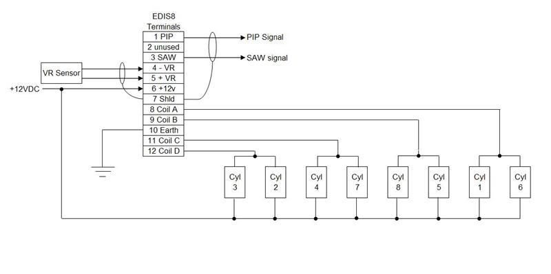
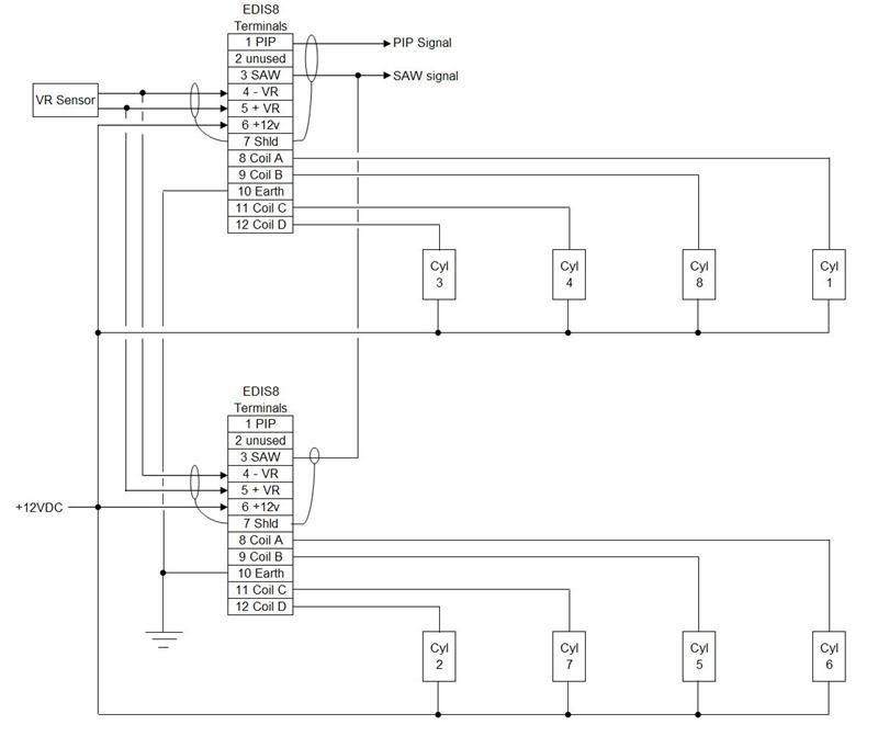
The reason I've exchanged the stock 12 tooth trigger wheel for a fabricated 36-1 tooth gear is so that I can temporarily use a standalone, tunable ignition made by Ford, called the EDIS8. I say temporary, because I plan to use this ignition only for the break in of my engine, then will probably dispose of it, and will use the ignition functions built into my standalone ECU for the permanent system.
Sorry for the long winded post here, but the evolution of ignition systems is a really interesting subject (for me anyway).