Chuck and Ryan's RCR Build

Chuck

Supporter
Rear Spoiler, Part I

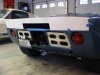
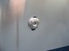
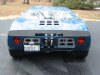
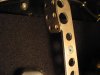
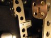
To add to the ‘race car’ look a spoiler was added, per Ryan's suggestion. After carefully studying pictures in The Ford That Beat Ferrari we concluded that there was no single right way to do it. Virtually every spoiler varied a bit. We settled on a design used on a Gulf GT, without the small lateral vent holes, as the best prototype. The lower edge lines up with the bottom of the center vent, six primary fasteners are used, and the fasteners are on the same horizontal line as the top edge of the center vent opening. The symmetry just seemed right.

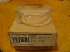
We called Fran at RCR and he supplied us with a nice spoiler fabricated from about a 3/32 inch thick piece of aluminum. It provided us with an excellent starting point but about two inches taller then we wanted and it did not have the center vent opening.

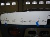
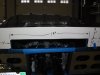
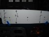
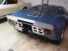
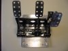
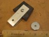
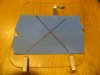
As is our practice, a pattern was made following the dimensions of the spoiler. This was taped to the car to help determine the best final dimensions and location of the center vent cutout. Once we were satisfied with the size and shape, the spoiler was cut with a jig saw. The cut edges were smoothed with a file and then with 80 grit sand paper. The spoiler was then polished with 600 grit paper followed by Mother’s Billet polish.

The pictures detail the dimensions. Not visible in the pictures is the front of the spoiler. The top of the spoiler extends about ¾” above the top edge of the clip.

Next we will drill the holes and install it.
 

Attachments

  • SpoilerPatternStart1.JPG
    SpoilerPatternStart1.JPG
    138 KB · Views: 670
  • SpoilerPatternLeft.JPG
    SpoilerPatternLeft.JPG
    104.4 KB · Views: 591
  • SpoilerPatternCenter.JPG
    SpoilerPatternCenter.JPG
    111.6 KB · Views: 591
  • SpoilerPatternRight.JPG
    SpoilerPatternRight.JPG
    82.3 KB · Views: 561

Chuck

Supporter
Rear Spoiler, Part II

Six holes were drilled for the fasteners. Typically slots were used to facilitate up and down adjustment. Since cruising at 150 MPH will not be part of our regular agenda, such fine tuning is not really an issue. So instead of a slot, we just drilled two additional holes, one above and one below the hole that is used to secure the spoiler, to create the appearance of a slot. The “slot” should probably be longer, but this is sufficient to create the effect.

We found very nice stainless fasteners which have a socket head bolt and a special billet washer. Billet Specialties, part number 66110, available from Summit Racing. Between the spoiler and the body, 2 ¼” diameter rubber washers were used. On the back side of the body 1 ½” fender washers distribute the pressure. Stainless steel nyloc nuts with a bit of anti seize holds it all together. The nut was put on snug, but not too tight.
 

Attachments

  • SpoilerBoltSlot.JPG
    SpoilerBoltSlot.JPG
    73.5 KB · Views: 621
  • SpoilerPartsBolts.JPG
    SpoilerPartsBolts.JPG
    118.2 KB · Views: 587
  • SpoilerInstalled1.JPG
    SpoilerInstalled1.JPG
    138 KB · Views: 675
  • SpoilerInstalled2.JPG
    SpoilerInstalled2.JPG
    194.5 KB · Views: 700
  • SpoilerInstalled3.JPG
    SpoilerInstalled3.JPG
    142.7 KB · Views: 681
Looks good, I am considering one for my car

Thanks for the detailed walk-through, I have always enjoyed your build and subsequent tweaks.

Kevin
 

Chuck

Supporter
Fire Suppression System

After 2300 miles of driving (including a great 40 mile ride Sunday in 35 degree weather) we finally got around to installing the fire suppression system. We kept it simple.

The tank is installed in the typical location under the front clip. The activating cable is run to the pull lever under the dash, parallel to the heater temperature control cable. The only tricky part was feeding the 3/8 OD aluminum tubing through the center tunnel and routing it up to the nozzle. The copper tubing that came with the system was not used since it was much too rigid to route. The aluminum can be easily bent to shape.

The visible sections of the aluminum tubing were covered with Painless wire wrap to make it less conspicuous. The tubing was secured with padded hose clamps.

No separate nozzle in the passenger compartment was installed. That is a project for another day.

We thought about pulling the lever and testing the system to see if it worked, but decided against it. Hopefully we will never have a need to discover the answer to that question.
 

Attachments

  • FireTank2.JPG
    FireTank2.JPG
    138 KB · Views: 529
  • FireNozzle1.JPG
    FireNozzle1.JPG
    190.1 KB · Views: 533
  • FireSwitch.JPG
    FireSwitch.JPG
    124 KB · Views: 535
  • FrontClipArea.JPG
    FrontClipArea.JPG
    176.1 KB · Views: 624
Speedometer calibration

The weather in Southern Illinois was perfect today, with clear blue sky and high temps around 70. Ryan and I decided to take the GT out on the highway for the first time. We took along the GPS so we could calibrate the speedo. When traveling at a true speed of 60 MPH the speedometer indicated 110. The speedometer was easily removed, thanks to the knurled knobs used to install it so many months ago, and the DIP switches adjusted so the following were open: 3, 4, 10, 12. This resulted in an indicated speed within a couple of MPH of the true speed indicated on the GPS. The speedometer read nice and steady with no fluctuations or ‘spikes’ of the needle

The short message: Preset the DIP switches to make the following open: 3, 4, 10, 12. That should get you within two or 3 MPH using the 15 inch tires supplied by RCR.

99% DONE ! ! !

Chuck what is your setting on the SN77

123 on 4 off

or

13 on 24 off

and what´s your front tire size ?


I made a little excel chart to find out how it works. I have come to slightly different result, but this may come from a different SN77 setting . The very basic assumption of this chart is that the speedometer default setting is calibrated to 60mph equals 16000 pulses per mile .

yellow fields are the ones to change

Thanks for your input

TOM
 

Attachments

  • SPEEDOMETER CALIBRATION.xls
    16.5 KB · Views: 268
Last edited:

Chuck

Supporter
Tom:

Pulled the front clip and cover. It is really hard to see the settings. As best I can tell it is: 1, 2, 3, ON and 4 OFF.

The manual also confirms these settings for a 16 pulse SN77 (which is probably why I did not post it in my original post. Sorry).

Tire size: 205 - 60R 15.

So does this mean you are getting close to a road test? ? ?

I was a bit skeptical of this set up, with a sensor picking up a signal from the brake rotor. But it has proven very reliable and accurate. Indeed it is more accurate than the BMW and Porsche speedos, which read fast by 5 and 3 MPH, respectively.

I calibrated the speedo off of a GPS. That worked well.

Good luck.
 
Thanks for that

makes sense, my chart was based on a SN77 setting of 13 on 24 off, which multiplies the received pulses by 4 before sending it to the speedo. The 123 on 4 of setting looks like having a multiplying faktor of 4,5.

Updated the chart and it looks good to me.

Yes first drive is not to fare away.

TOM
 

Attachments

  • SPEEDOMETER%20CALIBRATION(1).xls
    16.5 KB · Views: 273

Keith

Lifetime Supporter
Chuck,
Sorting out the speedometer was one of the more difficult issues I had during my build. I have the 8 pulse unit and I had a difficult time getting a "good" signal using the bolts from the brake rotor to the hub. The instructions with the speedo pick up called for a .060 gap between the pick-up and the end of the bolt. With a .060 gap I had no signal; as I closed the gap I got a signal but it was a "dirty" weak signal as the tapered locking nut was close enough to the end of the bolt so the the pick-up did not see a clean brake as the bolt passed by. I ended up getting longer grade 8 bolts and machining them to an exact length so that I could close the gap to .010. With this change the speedo worked well but I still had to calibrate it. I made an "extension cord" so that I could drive the car with the speedo in my lap and just stop at the end of each run and change the dip switches and make another run. It took three sessions of about an hour each and about 20 miles to get it where it is now. I finally settled on having it "spot on" at 60 mph, just short of 3 mph fast at 30 mph and just short of 3 mph slow at 90 mph based on my GPS. I used several different dip switch settings and finally figured out that this was the best I could do.

Where did you get your fire supression system............It looks great and it is close to the last thing I have left to do befor I can call mine "complete".

Keith
 

Chuck

Supporter
Keith:

Sounds like you had quite a struggle with your speedo. Wonder if the SN77 16 pulse may be more sensitive than the 8 pulse system. Don't know. I do recall going to great lengths to shield the signal wires, and independenly ground the various components out of fear that a stray signal might affect the performance.

Regardless, if you get a variation of only +/- 3 mph at ends of your speedo's range I would say you are getting an excellent result. That is better than most production cars.

I can't recall if I ordered the suppression system myself or if I ordered it through Fran. I note that currently most of the systems are Halon, which would be preferrable to my older style system. The current equivalent to what I used would be a Safecraft LT10AAB.

Safecraft LT10AAB - Safecraft LT Series Fire Protection Systems - Overview - SummitRacing.com

In the post reference is made to 3/8" line. That is wrong. It is 1/4" line.

Chuck
 

Chuck

Supporter
Brake Pedal Redo

When the brake pedal assembly was originally installed, a CNC adjustable pedal mount was used to make the pedals adjustable. It worked, but since the plate was only about four inches wide the pedal assembly tended to flex a bit and caused us some concern. We wanted a more rigid method for mounting the pedals. Coincidentally, while visiting RCR last month, we mentioned the issue to Fran. He had already solved this problem. We came home with a new mounting plate.

The design is essentially the same as the CNC, but it is much wider. In addition we mounted the plate to the pedal assembly and the pins to the floor – just the reverse of how we mounted the CNC plate. The result is a much more rigid assembly.

A word of advice: use washers between the pedal assembly and the mounting plate in order to prevent the fastening pins from dragging on the bottom of the pedal assembly when sliding it to disengage the pins. It will be very difficult to slide the pedal assembly loose if you fail to use washers to space the pedal assembly slightly above the plate.

While we had the pedal assembly out of the car, we cleaned it and repainted it (our pedal frame is one of the pre stainless steel versions). We also sought some way to reduce the amount of lateral ‘play’ in the pedals.

Brass sheet stock, .005”, was cut to the same length as the openings in the pedal bolt sleeves and formed into a tube. Slipping the shoulder bolt in place was a snug fit, which is exactly what we wanted. A bit of grease was applied. This worked very well, reducing the lateral movement of the pedals giving them a nice, tight feel. The clutch pedal is shown in the picture. ( We had done the same thing when we originally started this build, but the brass sheet used back then was too thin.

We made an interesting discovery. The pin securing the push rod to the clutch pedal had a deep grove worn into it, a good part of the way through. We replaced it with a shoulder bolt. We were surprised to see that degree of wear in only 2500 miles. We would have lost the use of the clutch had it failed under way. We had not put any grease on that pin, which may have been a factor. There was no wear on the stainless pedal arm, only on the pin, suggesting it was fabricated from a rather soft metal. That is an item worth checking if your RCR has some miles on it. A picture is attached.
 

Attachments

  • PedalBushing2.JPG
    PedalBushing2.JPG
    139.9 KB · Views: 542
  • PedalAssembly1.JPG
    PedalAssembly1.JPG
    115.8 KB · Views: 527
  • PedalsInstalled1.JPG
    PedalsInstalled1.JPG
    169.8 KB · Views: 523
  • PedalsInstalled3.JPG
    PedalsInstalled3.JPG
    167.7 KB · Views: 568
  • ClutchPedalPin.JPG
    ClutchPedalPin.JPG
    84.5 KB · Views: 488

Chuck

Supporter
Clutch Pedal Stop

To make sure we did not stress the master cylinder or slave cylinder we finally got around to adding a clutch pedal stop. Our requirements were (1) simple and (2) install without having to take anything apart.

With the clutch pushed all the way in we measured a distance of 1 inch from the back side of the pedal to the closest point on the pedal frame. We wanted to stop the pedal about a quarter inch from that last bit of travel. So a rubber spacer about 1 3/8” was needed, accounting for some compression.

Two 2 1/8” lengths of ¾” x 1/8” aluminum were used to hold a quarter inch thick section of rubber cut to a length of 1 3/8” inch. Four M6 metric washers were used to center the screw holding the two aluminum plates to the pedal. (The metric washers fit nice and snug).

The rubber stop was cut from a quarter inch thick rubber washer, 2 inches in diameter. Don’t’ fret over the center hole being too big. Once squeezed between the aluminum plates with a small screw it won’t matter.

One could cut the rubber washer a bit wider than 1 3/8 and then trim it to fit for a specific application, depending on the specific master cylinder being used..

This is about as simple as it gets. And it works just fine. It is nice to have a bit of a cushion at the end of the pedal travel rather than the more abrupt feel of the master cylinder reaching the limit of its travel.
 

Attachments

  • ClutchPedalStop1.JPG
    ClutchPedalStop1.JPG
    128.3 KB · Views: 398
  • ClutchPedalStop2.JPG
    ClutchPedalStop2.JPG
    114.7 KB · Views: 364
  • ClutchPedalStop4.JPG
    ClutchPedalStop4.JPG
    169.5 KB · Views: 409
  • ClutchPedalStop7.JPG
    ClutchPedalStop7.JPG
    153.3 KB · Views: 446
Chuck, you might be able to make life slightly easier on the clutch diaphragm if you check the pedal height that 'you need' in order to select reverse gear from a standstill then adjust the pedal stop to that depressed pedal height plus a bit more, pushing the diaphragm past 'that point' weakens the diaphragm over time.
 

Randy V

Moderator-Admin
Staff member
Admin
Lifetime Supporter
Nice work guys and thanks for the heads up on the pin wear!!!
 

Chuck

Supporter
Jac Mac: Thanks for the tip. Your description for adjusting the pedal stop is just about exactly how our set ended up.
 

Chuck

Supporter
Window Vent

We wanted a bit of fresh air on mild days rather than running the AC. The Gulf cars often added an aircraft type vent centered on the side opening vent. Typically they were used only on the driver’s door. That was the prototype for this addition.

The Snap Vent is available from several sources including Aircraft Spruce, P/N 05-01179, CC 3251, 3 ¼” diameter. A 3 ¼ hole was drilled with a hole saw at slow RPMs to prevent melting the plastic after putting masking tape on the window to protect it from scratches.

A small piece of adhesive felt pad, cut to about 1/4” x 1/8” (Ace Hardware) was added by the tab that serves as the pivot point when the vent is opened and closed. This snugged up the fit a bit and helps the vent rotate more smoothly. Also notches where filed near the spring wires holes to make the vent ‘snap’ in place when it is opened, helping it remain more reliably in the open position. (The notches do not show up in the photos.)

It was in the upper sixties and sunny when the GT was driven this past Saturday. This little vent brought a nice flow of air into the cabin towards the left side of the driver’s head. This is an easy, inexpensive, prototypical, and functional addition.
 

Attachments

  • Vent1.JPG
    Vent1.JPG
    134.2 KB · Views: 498
  • Vent2.JPG
    Vent2.JPG
    112.8 KB · Views: 455
  • Vent4.JPG
    Vent4.JPG
    120.8 KB · Views: 518
  • Vent5.JPG
    Vent5.JPG
    161 KB · Views: 575
Back
Top