Chuck and Ryan's RCR Build

Chuck great idea and as allways perfect execution.

Another option would be this one.
bootsanker-102946.jpg

if you mount it on top of the rear clip, it could serve as aerodynamic add as well. I would connect it to the rear roll bar with a high tec carbon fiber rope, to save weight. THe only thought you have to put in, is the release mechanism, if you want to use it as emergency brake instead of just a parking brake.

Happy Easter

TOM
 
Last edited:

Keith

Lifetime Supporter
Tom,
The dog sled guys in the far north use a similar device and it is very effective, but like Chuck and Ryan, I have been using a similar device made from a 2x4 so I could save the money for things like cup holders and noise supression devices.
Keith
 

Ian Anderson

Lifetime Supporter
I love Chuck's annual posts

Brilliant

All I managed was to mix some ENO with the sugar in the bowl at work. Foaming coffee always gets a smile

Ian
 

Jim Rosenthal

Supporter
Funny, I have a parking brake just like that on my boat. Well, almost; that's a Bruce parking brake, and mine is a Fortress, but you get the idea.
 

Chuck

Supporter
Header Heat

On our first drive this spring the heat from the header made the fiberglass a bit soft. One of the pipes was less than a quarter inch from the fiberglass. The way the opening in the clip around the carburetor was cut created a lip, so the edge of the fiberglass was almost in direct contact with the header.

A section of aluminum 18” x 8” was used as a shield. It was bent to follow the inner contour of the clip. Reflective heat shielding material was cut to shape and attached to the bottom of the a aluminum.

Next the lip on the opening in the clip was tapered back along only the aft edge so that it was about a quarter inch away from the pipe. One really is not even aware that only the back edge of the opening is tapered in this manner. It blends in well.

A Click Bond Stud Kit was ordered from Aircraft Spruce, Part # 04-06020 (small). This is a clever little device that epoxies a screw to the inside of the fiberglass providing a connection point that is not visible from the reverse side. Nicely engineered. After cutting away the existing insulation and making our usual pattern, four were applied. Thanks to Lynn Erickson for suggesting this item.

A second layer of the reflective heat shielding material was placed over the area on the underside of the clip carefully cutting out four holes to clear the four click bond studs.

A layer of insulation was placed between the shield and the fiberglass. Aircraft Spruce, Fiberfrax 970J, Part # 05-02679. This is a light material only an eighth inch thick with a very high temperature rating of 2300 degrees F. It is inexpensive and easy to work with. Lynn Erickson recommended this item as well, which was a great tip.

A second shield approximately two by three inches was cut from a scrap piece of stainless steel. A piece of Fiberfax was cut the same size. This was held to the larger shield with a couple of pop rivets. This is the point where the header pipe comes in closest contact with the clip. Indeed when the clip is closed the pipe will just kiss this second shield.

We have taken a couple of good drives long enough to get the engine thoroughly warmed up. Using the palm of the hand no difference in temperature could be sensed between the area directly above the headers pipes and the surrounding areas of the clip. This approach will hopefully resolve the issue.
 

Attachments

  • HeaderInsulation5.JPG
    HeaderInsulation5.JPG
    128.6 KB · Views: 570
  • HeaderInsulation2.JPG
    HeaderInsulation2.JPG
    173 KB · Views: 587
  • HeaderInsulation3.JPG
    HeaderInsulation3.JPG
    118.2 KB · Views: 538
  • HeaderInsulation4.JPG
    HeaderInsulation4.JPG
    134.2 KB · Views: 561
  • HeaderInsulation6.JPG
    HeaderInsulation6.JPG
    174.1 KB · Views: 605

Randy V

Moderator-Admin
Staff member
Admin
Lifetime Supporter
Well done Chuck - I'll be using a similar approach on the rear of my clip...
 

Chuck

Supporter
Clip Clasps

A couple of features that made our GT look unoriginal are the clasps holding the clips closed and the “Wilwood” lettering on the calipers. The brakes work great and we have no intention of making any changes to them. But the clasps were a different story.

Original style claps cost an arm and a leg. But Fran found a supplier at a more reasonable price. So we ordered a set from Fran.

The lower bracket was secured to the fiberglass with a pair of Nutserts. Since these clasps really don’t carry much load this should not be a problem. (Hood pins keep the rear clip securely closed).

They are easy to open and close and look much like the originals.
 

Attachments

  • ClipClip1.JPG
    ClipClip1.JPG
    138 KB · Views: 661
  • ClipClip2.JPG
    ClipClip2.JPG
    128.3 KB · Views: 661

Chuck

Supporter
Shift Plate

The shift box, black powder coated with large openings on both sides, may be a nice bit of engineering but does not really capture the look of an original GT. It needed something. We did not want to cover it completely, just dress it up a bit retaining the ‘mechanical’ look.

So we asked Fran if he could fab a cover plate. The RCR crew made a plate perfectly matching the interior cut out of the shifter box with symmetrical outside dimensions. We sanded it with 400 grit to get some marks out, followed by 800 grit and then come billet polish. It polished up nicely.

It is held in place with Scotch double sided tape. Not the white foam stuff, but clear. This was a new product to me. It is thinner than the foam tape and really sticks.

Simple and easy.
 

Attachments

  • Shifterplate5.JPG
    Shifterplate5.JPG
    113.8 KB · Views: 686
  • Shifterplate1.JPG
    Shifterplate1.JPG
    113.8 KB · Views: 498

Chuck

Supporter
Reversion Plate

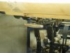
The eight throats of the Weber carbs make an impressive sight that sets the GT apart from many lesser conveyances. But that awesome look is not really original. The Mark I GT 40 had a reversion plate mounted above the Weber carbs. The Webers were hidden from view. Its purpose has been variously described by different sources as protecting the Webers from errant debris being dropped inside, protecting the rear glass from backfires, or maximizing the flow of air into those eight throats. That later is likely the primary purpose.

The point, however, is that an accurate reproduction should have a reversion plate covering the carbs. But who in their right mind wants to cover the carbs? How about the GT that uses a single four barrel instead of Weber carbs?

A Holley type carb just does not look right on a GT, Mark I. So we sought a way to conceal the dreadful truth – that we no longer had Webers.

There was some variation in the style of reversion plates used on the originals. The early Mark I used a setup ideally suited to our needs. A rectangular shape with a downward lip, supported by five bolts mounted on a flat pan at the base of the Weber’s air horns. Easily duplicated.

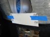
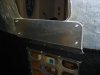
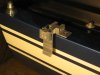
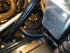
We made up the usual pattern. The dimensions were 18 inches by 12 inches with a three quarter inch lip. The corners have a one half inch radius. Once satisfied that it would clear the clip, cover the carb, and not interfere with the glass, we contacted Fran at RCR and asked if he could fabricate it for us.

The RCR crew did an excellent job. The cover is made from a hefty piece of aluminum, the corners are nicely curved, and the inside corners welded in typical RCR fashion.

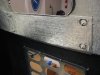
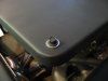
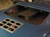
Five holes were drilled for quarter inch bolts. The four corner bolts are non functional, intended to duplicate the look of the original

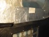
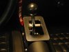
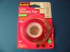
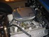
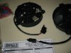
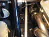
An oval billet aluminum air cleaner was purchased. (Summit BSP-15329). It was not cheap. But the smooth top plate provided a good mounting surface for the reversion plate. The last bolt hole was drilled dead center and the screw goes directly through the billet cover plate into the carb. A couple of strips of 1/16 inch foam tape keep it from sliding.

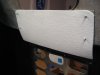
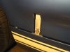
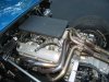
The aluminum reversion plate was sanded with 400 grit followed by 800 grit paper. It was primed and again sanded. Then it was painted our usual engine low gloss black. It matches the inner area of the rear clip perfectly.

A lower plate and deflector to reduce head from the collectors affecting the carb could be fabricated, much like the early Mark I GT. That may be our next project.

At some point we may move up to Dyna Tech fuel injection. But for now we have a really sweet running engine, well suited to frequent road trips, that looks similar to the original early Mark I.
 

Attachments

  • ReversionPlate8.JPG
    ReversionPlate8.JPG
    177.6 KB · Views: 571
  • Reversionplate9.JPG
    Reversionplate9.JPG
    119.2 KB · Views: 578
  • ReversionPlate10.JPG
    ReversionPlate10.JPG
    189.7 KB · Views: 699
  • ReversionPlate3.JPG
    ReversionPlate3.JPG
    139.8 KB · Views: 640

Chuck

Supporter
Blow Job

The persistent summer heat has not prevented us from driving the GT. The air conditioning makes an evening drive in ninety plus heat quite manageable. But the engine compartment does not seem to be faring as well.

Lifting the clip after an hour drive in ninety plus heat revealed a worrisome issue. The fiberglass above the engine was very hot to the touch and soft, almost pliable. There was no visible damage, but such high temperatures can’t be good. One can’t always raise the clip after shutting down when stopping away from home.

It seems that the hot air stagnates below the clip above the engine. At low speed I suspect there is little air movement. Driving in traffic is tough to avoid. So a means of moving that air was sought.

There are two five inch diameter access openings on the sponsons. They come drilled and tapped for a cover plate. Air drawn from that opening enters from the rear of the sponson; seemingly an ideal source since it is low where the air is cooler and in a area where the aerodynamics of the car should not affect the air flow.

We found the perfect fan for this application. Derale Cooling Products, Part number 16505, available from several sources including Summit. It is five inches in diameter and fits perfectly over the opening on the sponson. It moves 325 CFM of air and draws 3.6 amps. Those are respectable specs for such a small fan.

The fans have three mounting tabs. Two line up perfectly with the existing holes for the cover plate. It was a simple matter to drill and tap the third. Quarter inch nylon spacers were placed below the mounting tabs so that the screws could be tightened down without damaging the mounting tabs.

The fans are only 1.250 inches thick and thus do not interfere with the suspension. Indeed, once installed they are difficult to see, blending in well.

The fans were wired through a relay. The relay is activated by a switch on the dash, giving us the option of keeping the fans on after the car has been shut down. When the car was originally wired an extra wire from the dash fan – override switch was run to the rear of the car for this contingency.

With a total of 650 CFM the fans blow plenty of air. Stopping after a brisk three quarter hour drive in ninety degree heat, one could feel the flow of warm air being blown from those fans at the openings of the rear of the clip above and on either side of the exhaust pipes. The fans move the air from the front to the rear of the clip effectively. This will supplement the natural flow from the side vents when driving at speed.

Most important, when the clip was lifted the fiberglass was not nearly as hot and did not have that soft, almost pliable feel.

The fans are loud. They sound like typical electric radiator fans. You won’t walk away from the car without realizing they are on. Of course the sound inside the cabin is subdued and not that noticeable compared to the sound of the engine a foot from your ear.

Yarn tell tales taped to the rear clip move noticeably when the fans are on confirming the flow of air out the rear of the clip.

Check out the video version . . . . .

http://www.youtube.com/watch?v=v0i3Htxd9I4
 

Attachments

  • FanClip2.JPG
    FanClip2.JPG
    116.2 KB · Views: 838
  • FanClip1.JPG
    FanClip1.JPG
    174.8 KB · Views: 950
  • FanClip4.JPG
    FanClip4.JPG
    159.9 KB · Views: 989
  • FanClip6.JPG
    FanClip6.JPG
    204.1 KB · Views: 989
Very inventive solution....as usual nice work...

Do you need a job ?...got a spare slot at the shop if you feel like a change of pace...wink
 

David Morton

Lifetime Supporter
With that gloved hand it's almost like something from Alfred Hitchcock. Some screams and a dark thunderstorm would make it a bit more wild. Neat job though. I seem to recall one of the mallock cars had something along those lines as well and directed into the area of the weber 48s.
 

Chuck

Supporter
Nice touch, the ominous black-gloved finger insidiously flips the switch to turn on the leaf blower.

Will a timer be employed?

Darth vader was looking for work, hence the black glove. He really is a nice guy as long as you keep him away from that light saber.

I am working on the timer circuit and will do another post once sorted out.
 
Chuck,
I have been looking at the same idea but with the Spal fans. They have almost the same CFM. If they have the same shrouding as your Derale unit I am going to go with them.I already have an opening in the same location as yours that I was originally going to close up, but will now utilize them with the fans(my welder friend just forgot to close them off). The Spal units are on sale right now for just under $50 and are compatible with the controller that I am going to use with the front fans and water pump. This will allow me to use the run on function controlled by the water thermostat. That should keep the fiberglass and my back a little cooler.
An idea I had before the fan controller, was to use a fused battery wire(hot all the time) to run the relays for the fan(s) and water pump. All would be controlled by a thermostat(relay ground to thermostat). If you have a belt driven water pump, mount the thermostat above the headers. If you have an electric water pump use the normal water thermostat. That way the fans(and pump) would turn on, on the high temp setting and off on the low temp setting and would not run down the battery. Wouldn't need a switch. This would cost you virtually nothing!! You wouldn't need any electronic timers or circuits. Well, its a thought. Anyone see why it wouldn't work?? Down side, you would have to pay Darth to just sit around and breathe!!

Bill
 

Chuck

Supporter
Bill:

Thanks for the ideas. Some thoughts.

1. I am keeping the radiator fans wired separate from the engine compartment fans.

2. Using the water thermostat to keep the fans on after shut down would make the time they run after the ignition is off unpredictable. Could wear down a battery or, even worse, make the neighbors wonder why that deserted car is still buzzing.

3. A timer on the engine fan compartment wil give certainty to the run time saving the battery. Perhaps one could vary the time so that in the dead of winter 2 minutes would be sufficeint but in mid summer 10 minutes might be best. But regardless one would know for certain when it would go off. Those two fans draw seven amps, so don't want to abuse the battery.

4. Since we have a conventional rather than electric water pump, there is no real reason to keep the radiator fans running after turning the ignition off. The coolant won't be moving.

5. I usually like the "keep it simple" approach. A year from now it makes it a lot easier for my feeble memory to figure out what the heck I was thinking back then.
 
Chuck,
Read it again. The fans in the rear clip are wired separately. Only wire it with the radiator if you have an electric pump. If you have a conventional pump, which you do, then set the thermostat over the exhaust. It will turn the fans on automatically and off automatically. My stainless exhaust when I cranked the engine for the first time, cooled down on their own rather quickly. I was amazed at how quick it was that I could put my hand on them. The moving air should do it even quicker. It would be worth a try anyway just to see how long it took.
I think you raise a good question though. How long would it take for a 7 amp draw to run a battery down??? Any takers on that one??

Bill
 

Russ Noble

GT40s Supporter
Lifetime Supporter
I think you raise a good question though. How long would it take for a 7 amp draw to run a battery down??? Any takers on that one??

Bill

Yeah, I'll have a go Bill! Depends on the size of the battery!!!!!!:lipsrsealed:

More specifically, if you're running an Odyssey PC680 as I am, rated at 17 amphours then approx 2½ hours. If you've gone for more capacity say a PC925 rated at 28 amphours then about 4 hours. But without knowing the capacity of the battery, you will have no idea. And very few of the run of the mill starting batteries list their a/h rating, only their CCA.

But who in GT40 land has a run of the mill anything? Only the biggest, brightest and best will do, so it's easy to work out. Divide the number of amphours by the amperage draw and you are in the ballpark.:stunned:
 
Back
Top