

You are using an out of date browser. It may not display this or other websites correctly.
You should upgrade or use an alternative browser.
You should upgrade or use an alternative browser.
DRB #5
- Thread starter wbmusarra
- Start date
I have been trying like heck to get some time to get the motor installed.As usual I ran into some projects I wanted to do, so I did them to get them out of the way. I added a 4 light LED strip to the footwells and a set for the overhead lighting at the rear of the cabin.
One thing that always sort of bothered me was the fact that there was no engine/trans support where they meet. Just the rear support that I built for the trans. Since all is solid mounted, it concerned me about flexing in that area, given all the torque that has been added, as there is a lot of aluminum in that area. I still had pieces of the trailing links that came on the car. They were woefully inadequate for that job. They were removed and new adjustable ones installed. As you may remember I used the T sections as a foot rest on the passenger side of the cabin. The bars were the right size for the support pieces.

So they were cut up. A plate was welded on for the trans end and a section of the tube was used for the motor mount section. Bushings were added to keep them from moving as the internal diameter was larger than the bolt.The new bolt will be either Nordlocked or star washered and Loctite added to keep them from working loose.


With only half of the trans adapter mounted to the engine, these bars should help prevent any flexing that might occur in that area. It is probably overkill, but it will make me feel a little more secure.
As you can see the motor is now in. Now all the accessorys and sensors have to be added and then it is ignition time. I am excited and worried at the same time as I am hoping the alternator problem is resolved.
Since adding the rear clip cooling fans, I changed the trans pump switch to the fan function, and put the pump on the same circuit as the trans fan(thermostat controlled), so it will control both functions, and gives me a trip mechanism for the cooling fans. The Waytech relay will have to be adjusted after the "big" power source is attached. The little 12 volt power source only runs on 6 amps and that is too low to try and set the run on timing.
Bill
One thing that always sort of bothered me was the fact that there was no engine/trans support where they meet. Just the rear support that I built for the trans. Since all is solid mounted, it concerned me about flexing in that area, given all the torque that has been added, as there is a lot of aluminum in that area. I still had pieces of the trailing links that came on the car. They were woefully inadequate for that job. They were removed and new adjustable ones installed. As you may remember I used the T sections as a foot rest on the passenger side of the cabin. The bars were the right size for the support pieces.
So they were cut up. A plate was welded on for the trans end and a section of the tube was used for the motor mount section. Bushings were added to keep them from moving as the internal diameter was larger than the bolt.The new bolt will be either Nordlocked or star washered and Loctite added to keep them from working loose.
With only half of the trans adapter mounted to the engine, these bars should help prevent any flexing that might occur in that area. It is probably overkill, but it will make me feel a little more secure.
As you can see the motor is now in. Now all the accessorys and sensors have to be added and then it is ignition time. I am excited and worried at the same time as I am hoping the alternator problem is resolved.
Since adding the rear clip cooling fans, I changed the trans pump switch to the fan function, and put the pump on the same circuit as the trans fan(thermostat controlled), so it will control both functions, and gives me a trip mechanism for the cooling fans. The Waytech relay will have to be adjusted after the "big" power source is attached. The little 12 volt power source only runs on 6 amps and that is too low to try and set the run on timing.
Bill
Well some of the pics got moved on Photobucket. So here they are again.

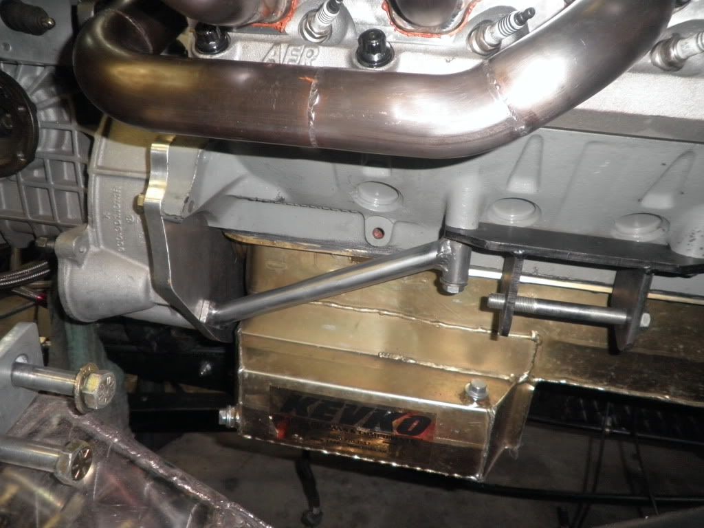
These are the trans braces since I don't have a mount to the frame. My concern was the possible flexing in this area as only half of the trans adapter is bolted to the engine and there is a lot of aluminum in this area.
Bill
These are the trans braces since I don't have a mount to the frame. My concern was the possible flexing in this area as only half of the trans adapter is bolted to the engine and there is a lot of aluminum in this area.
Bill
Well, I have been working on the car, but the progress is as usual,, slow. My wife has decided that it is time to redo the kitchen cabinets and countertops along with the replacing the carpeting in the living room with hardwood floors. What's a guy to do????
The engine has been rebuilt and the pistons fly cut for the big AFR 205 valves. Since the engine was out of the car I finally got around to several small projects that were sorely needed. One was the alternator. During the test runs before the valve problem arose, I had noticed the alternator belt was being chewed up and belt dust was everywhere. The alternator was suspended by a strap and bolt at the top and the bottom was held on by one bolt off the front cover. Unfortunately the crank trigger was supported by this same bolt. So every time I had to add tension to the alternator, it would pull the trigger with it. Needless to say the .005"clearance would be off.

So I undertook a new one. I had two AC brackets that came with my compressor. They weren't the proper opening, but a plasma torch and Mig welder made short work of that.

I had to grind away the old sensor hole on the front cover to get at two mounting bolts that were needed to give proper support to the alternator. Actually it gave me three supports.

I also had to redo the hydraulic line for the clutch as I wasnted a safety switch for the ignition switch. So a stop light switch needed to be installed. While I was at it, the stop light switch was added to the front braking system.There is mot much room in the DRBs for the master cylinders. The one for the clutch nearly butted up against the frame support for the steering rack. So a hole had to be placed for it to fit.
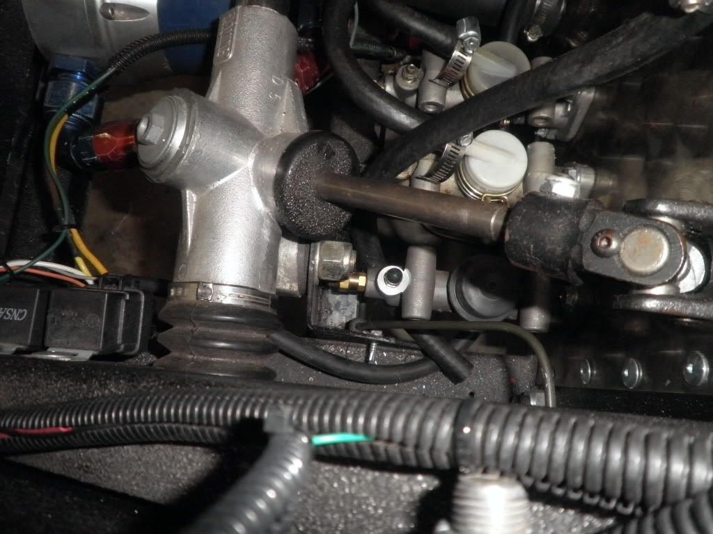
That process is nearly done as the new Tilton unit I got for the clutch had a different depth for the line to hook into. A double flare with its longest thread screw would not bottom out and the hose would move in and out. After searching high and low for an adapter which I was told was a JIC fitting, nothing could be found. I finally found a hydraulic hose shop that told me they had never heard of the JIC fittings and the problem wasn't the depth of the hole but it was that a fitting had to flush mount to the MC face was needed. They found the adapter for the Master Cylinder. All other pieces held pressure with their tester. Now to hook it all up and see if it works. Myengine builder finally got to come over and fire up the engine again. So now with a little tuning it will be good to go. I added some insulation to the water pipes in the form of closed cell units from Home Depot.

Since I had 1 1/2-2" pipes, I got the 3/4" pieces and taped them together. Man it that tunnel a tight fit now.
Bill
The engine has been rebuilt and the pistons fly cut for the big AFR 205 valves. Since the engine was out of the car I finally got around to several small projects that were sorely needed. One was the alternator. During the test runs before the valve problem arose, I had noticed the alternator belt was being chewed up and belt dust was everywhere. The alternator was suspended by a strap and bolt at the top and the bottom was held on by one bolt off the front cover. Unfortunately the crank trigger was supported by this same bolt. So every time I had to add tension to the alternator, it would pull the trigger with it. Needless to say the .005"clearance would be off.
So I undertook a new one. I had two AC brackets that came with my compressor. They weren't the proper opening, but a plasma torch and Mig welder made short work of that.
I had to grind away the old sensor hole on the front cover to get at two mounting bolts that were needed to give proper support to the alternator. Actually it gave me three supports.
I also had to redo the hydraulic line for the clutch as I wasnted a safety switch for the ignition switch. So a stop light switch needed to be installed. While I was at it, the stop light switch was added to the front braking system.There is mot much room in the DRBs for the master cylinders. The one for the clutch nearly butted up against the frame support for the steering rack. So a hole had to be placed for it to fit.
That process is nearly done as the new Tilton unit I got for the clutch had a different depth for the line to hook into. A double flare with its longest thread screw would not bottom out and the hose would move in and out. After searching high and low for an adapter which I was told was a JIC fitting, nothing could be found. I finally found a hydraulic hose shop that told me they had never heard of the JIC fittings and the problem wasn't the depth of the hole but it was that a fitting had to flush mount to the MC face was needed. They found the adapter for the Master Cylinder. All other pieces held pressure with their tester. Now to hook it all up and see if it works. Myengine builder finally got to come over and fire up the engine again. So now with a little tuning it will be good to go. I added some insulation to the water pipes in the form of closed cell units from Home Depot.
Since I had 1 1/2-2" pipes, I got the 3/4" pieces and taped them together. Man it that tunnel a tight fit now.
Bill
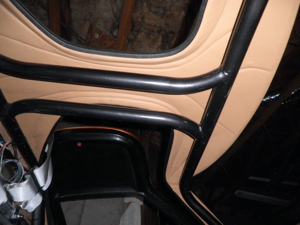
Things have progressed both forward an backward since the last post. The center console is in place and ready for the upholsterer. The seat mounting hardware has been altered to fit better and not interfere with the lap belt mounts and the cables to the shifter. The submarine mounts have been installed. While mounting the seats, I noticed the shoulder harness mounts with their 3 bar mount hardware, hit the seat and actually protruded into the slots in the seat. The RCI units that I have are actually replacements for the belts I originally had because they had expired. The company asked me when I sent them in if I wanted to go to the six point system at no charge other than the $20 refurbish fee. I agreed and they then informed me that the color would no longer be black but would be silver. I believe they were discontinuing the black units. I agreed and they sent them. They have sat in the shipping box for some time since and had not been mounted til now. The submarine straps are the cheaper version where they have the hardware sewn in(latch link setup). I tried them but did not like the fit. So they are going to be replaced with a Schroth, OMP or G-Force and a cam lock setup. In order to get the shoulder strap mount interference out of the way I may add a cross bar behind the seat to mount the belt using a wrap technique. Schroth has some neat hardware that eliminates almost all of the distance from the mount to the seat, allowing the seat to be back almost against the bar. They also use the 2" lap belt with a 3" sholder harness. The 2" lap belt is supposed to be superior in that the 2" stays below the crest of the hip bone(illiac crest). the 3" goes over the crest and can ride up over it putting the force on the abdominal contents. I am still looking into this.
So this is a bit of a setback in that the bar will have to be done carefully, and keep the sparks from shooting all over the place, and to get it painted without getting over spray on any of the leather that is already in the car.
Since the last start up, one would think the car would be up and running around. Well like all my projections, this one bit the dust as well.
The engine was running fine but a bit too fast around 1200 RPM. So I started working on getting the idle down. I noticed that as the idle got down below 1000 rpm, the engine would begin to labor and "knock" as if the timing had changed. I would pull the idle back up each time I tried and reported it to the builder and he said to leave the idle high til we set it up in his shop and we could check it out on the computer and the chassis dyno if need be since we plan to dyno the car anyway. The last time I cranked the car, the same thing happened after running the car for about 10 minutes. temps were normal, pressures were normal. Still running a bit rich. The idle was around 1500 so I worked it down to about 1000 and it began to labor again. Before I could adjust the idle screw up a bit the engine quit. Tried to crank it and the engine started spitting and popping, backfiring out the exhaust and up the injectors on at least three cylinders. If the ignition button were held while cranking it acted like it was flooded and the timing off with an erratic start. A couple of cylinders fired correctly but the others didn't fire at all or they backfired through the injectors and wouldn't start. When the builder showed up at the garage the next week end, the fuel pumps would not turn on. Tried everything I could think of, but they would not work. The only work that I had done while waiting for him to show up was to install the center console. In doing so I shorted a wire to the fuel pump safety switch. I checked all the fuses and replaced the one to the fuel pumps and repaired the wire. Silly me, I didn't turn them on to see if they would work after that. So he left to do some work in his shop. It took me two hours of searching and when I couldn't find anything, decided to check my wiring diagram and trace everything out to see if I had missed something. The builder was going to come back later that day and I was going to quickly wire the pumps directly bypassing the safety switch if I couldn't find anything. When I looked at the diagram the first wire from the battery goes to the inertia switch. I then saw I had tripped it . When it was set the pumps ran perfectly. On his return later on, we tried everything we could to sort the problem. We even went through the original start up routine to make sure the Hall sensor to the cam was correct, thinking that when the motor died, it had shifted the sensor somehow, even though the engine doesn't really need that sensor to run.
As a last resort we traced the wiring to each of the coils. I am running LS coils which are wired a little different than the Ford coils(one wire instead of two). We just had to wire the coils like the LS set up, but with the Ford firing order. What we found was that the #3 and #8 cylinders had been transposed when his shop personnel wired it. How it was running with it this way is beyond me. We cut the wires and reconnected them the way they should be. The engine stopped backfiring as bad but still acted like it was flooded and the timing was off with a hesitant starter and only 2-3 cylinders firing as they should. We pulled the plugs and replaced them with new units, but got the same results.
What didn't make sense was the engine running fine, it is spark knocking under 1000 rpm, and dies. Then won't crank and acts like it is flooded, and the timing is off. Our conclusion is that the computer is off. So we pulled both the XIM & XFI boxes and have sent them back to the factory to be inspected.We checked the wiring to the coils against the wiring diagram making sure they are going to the correct cylinders and have continuity.
My builder is an expert with Ford engines. He runs the worlds quickest Mustang and was first to break the 200 mph barrier on the drag strip in one. He does all the tuning for John Kasse who has won the Popular Hot Rodding Engine Masters series twice with Ford engines and got a third place this year with a Chevy Big Block.The competition is a points based set up. Numbers are based on an average of torque and horsepower from 2500 rpm to 6000 I believe, so raw horsepower won't win it. Each year they change the displacement of the engines. Small block one year, big block the next and so on. All of his motors use the FAST technology. So the builder knows his stuff. If FAST says the computer is O K we will have to get a new harness. Back when I had the valve to piston interference problem I shortened the harness as it was wired like it was a front engine setup. When I put it around the front of the engine it was a mile too long. So it was shortened. All cuts were soldered and shrink wrapped. All the wires were checked for continuity after they were completed. We did continuity checks on all the coils and they were perfect except for the two wires that were transposed. I even reset the butterfly valves.
So it will be a slow go for now. Hoefully we can get the boxes back in a week to ten days. The big snow has held us up this week. Atlanta has been paralyzed for the last 2 days with 4 inches of snow and 1-2 of ice. With temps below freezing all week and lows in the teens. it will be real slow.
Bill
The XFI boxes came back with the report that all was well. So now it goes to the detective stage of trying to find out what has caused the erratic behavior of the engine. I did some searching on the forum and found a somewhat similar situation with the XFI setuup except it was on a FE engine. They finally found that the oil pump gear on the distributor had sheared. The guys at Comp cams(bought out FAST) advised three things to check. One was the crank trigger. They had one case that the set pin in the crank pulley sheared(1 in a million shot) altering the pickup. The second thought was that the cam sensor might have sheared its oil pump gear. Usually seen when high output pumps were utilized. Mine has stayed in the 40 range when up to temp, and a bit higher when first started. I plan to pull the distributor shaft anyway, because this seems to be a timing issue. A quick check of TDC should let me kinow about the crank pulley. Pulling the pulley and the dampner is a thrash with the engine moved forward. I would have to raise the front of the motor just to check it. Their third idea was to treat the engine as if it was the first start up and go through their start up procedure, which we had already done.
Does anyone have any other ideas to consider?
Bill
Does anyone have any other ideas to consider?
Bill
I managed to pull the distributor housing without pulling the engine. My engine is moved forward and the aluminum fuel runners of the TWM set up block the vertical path above the housing. I found a bad wear pattern on one side of the oil pressure gear, and it looks like it may have skipped a tooth as about three teeth had worn to the point of having a razor edge rather than a square edge. The cam is billet steel and the gear was cast iron. Comp cams has a composite replacement. These are designed to correct the problem. The only alternative is a brass unit that is designed to wear out after a couple of thousand miles and is meant for the serious racer that tears their engines down after each meet. Acording to Comp cam the camshaft is designed to move about .020" and the cast iron is unforgiving. Should have the motor running by this weekend "hopefully".
Bill
Bill
Bill did your builder check the gear to block clearance? If it is binding when tightened down it is going to wear down in no time.
Dist. gear failure on SB Fords - FFCars.com - Factory Five Racing Discussion Forum
Dist. gear failure on SB Fords - FFCars.com - Factory Five Racing Discussion Forum
We discussed the problems that can come up with aftermarket distributors, especially the MSDs. We talked about each one that was mentioned on FFC and how to tell and the cures. I have passed it on to him. The gear wear pattern covered the entire gear top to bottom, so the shaft is settling to where it should. No forcing down etc. He mentioned one that I didn't see on their list was the bottom of the gear showing wear or scraping on the bottom of the gear itself from impropper placement. Thanks for the info. It should prove interesting to others. BTW on the chart they showed, the .531 shafts are 351s only. The chart is incorrect, they aren't 302s. they are smaller. The 351s and the 460s use the same shaft.
Bill
Bill
I have taken the car out to the fiberglass shop for some work that needs to be done. Adrain has moved his shop to his home shop and it eliminates his overhead and he can give me a break on labor charges. The cost of the work he and I have been discussing for several months is cut by 40%. Now I can get the car repainted along with the fiberglass work it needs. Since the car has sat for several years without a windshield, the roof has begun to droop. Z clips will be bonded to the roll cage and the fiberglass so as to raise the top to the proper height, and the B pillars will get the support they need. The hydraulics I installed some time ago for aiding the front clip are causing an alignment issue and will be reconfigured. The rear clip was trimmed about a year ago to fit better, but with it sitting off the car for that year, it too has changed its shape a bit. Once the pull down clips are added it will begin to settle in to where it belongs. The rear view camera(s) have been ordered and Adrian will build an enclosure for the main camera, which will be mounted on the center of the roof just in front of the rear clip. The other two cameras will be mounted in the side mirror housings. If that goes as expected, it will be fairly hard to detect their presence. The monitor, displaying all three cameras at once, will be housed in a center console between the dash and the gear shift. If this proves to be too tight, it will be suspended from the roll cage.
On the engine issues, the new composite gear for the oil pump has arrived and should be installed this week. Once all the other pieces have been reconnected the start up will begin AGAIN!!
Bill
On the engine issues, the new composite gear for the oil pump has arrived and should be installed this week. Once all the other pieces have been reconnected the start up will begin AGAIN!!
Bill
Hi Bill,
My car has suffered from Spider Droop as well although I've had a support strut in the center for the last couple of years.
I've started in on making other changes that will support the front section of the roof that extends forward of the cage and while I'm not quite finished enough to make a post specifically about the process, I thought I would share some pictures.
First I made a template out of cardboard;

Transferred to steel sheet metal for both left and right sides;

Welded (tacked) into position;

I will box in these supports with the spider removed form the car in order to create a fully supportive structure.
Here's a shot including one of the forward tabs that I've tacked to the cage and will bolt the spider to it and it's mate on the other side as well as a pair of them at the rear of the spider. I'll be using steel Nutserts into the fiberglass of the spider.

The Center support structure will also serve as a great mount for my rear view mirror.
The entire cage will be powder coated once the welding is all completed.
My car has suffered from Spider Droop as well although I've had a support strut in the center for the last couple of years.
I've started in on making other changes that will support the front section of the roof that extends forward of the cage and while I'm not quite finished enough to make a post specifically about the process, I thought I would share some pictures.
First I made a template out of cardboard;
Transferred to steel sheet metal for both left and right sides;
Welded (tacked) into position;
I will box in these supports with the spider removed form the car in order to create a fully supportive structure.
Here's a shot including one of the forward tabs that I've tacked to the cage and will bolt the spider to it and it's mate on the other side as well as a pair of them at the rear of the spider. I'll be using steel Nutserts into the fiberglass of the spider.
The Center support structure will also serve as a great mount for my rear view mirror.
The entire cage will be powder coated once the welding is all completed.
Randy,
That is some good work you are doing with your support. I go out to see the progress tomorrow and will take some pics of the finished product. I hadn't noticed the movement of the fiberglass until Adrian brought it up. I always thought the front wind screen was supposed to be gaped a bit!! Adrian explained how the fiberglass has a tendency to move around with the temps cycling and unsupported. I had stored the rear clip on its front mounting face and was amazed at how much it had moved when I put it back on the car. It really affects the mating and gaping of the panels and makes that job a real challenge.
We are working with a handicap in that the headliner is already in.
Fortunately Adrian is an upholsterer as well and will work it into the repair. He likes to do a lot of bonding so that is the plan for this area. 3M has some good products in a 2 pack setup. The metal pieces will shear before the bond releases. We plan to use this also for the fiberglass as the spyder will never be removed.
Bill
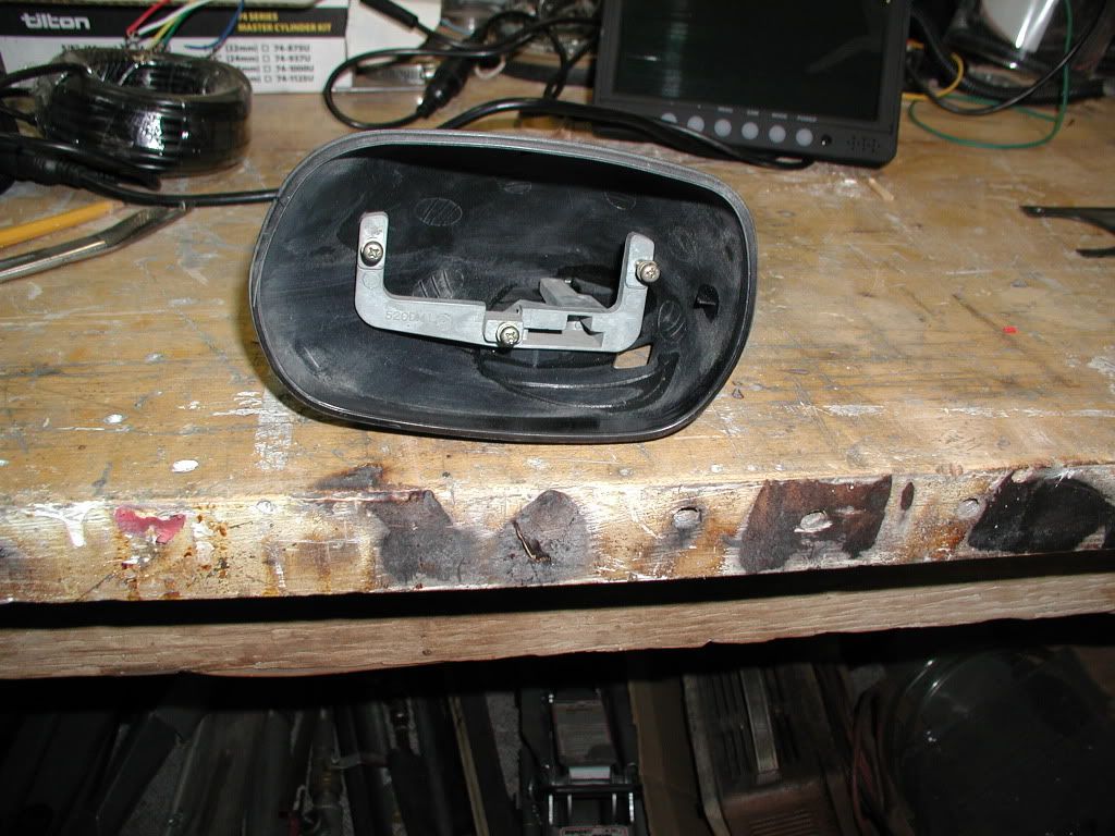
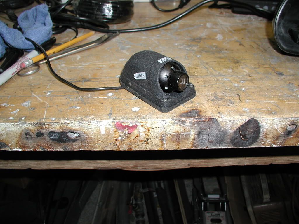
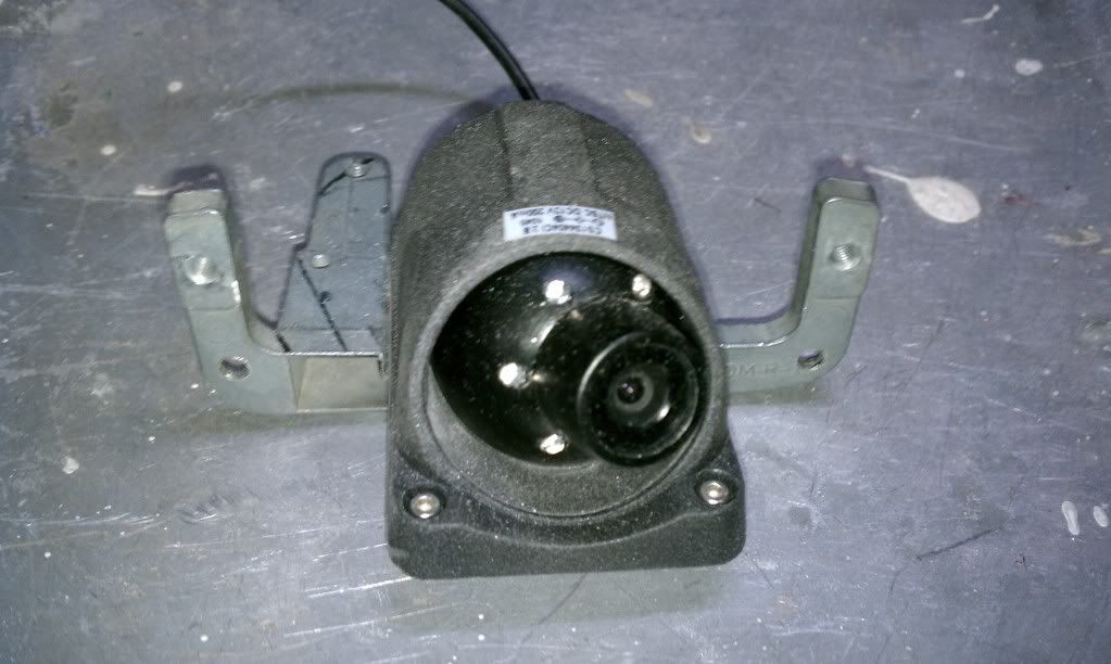
Well I finally made it out to the shop and,,,,, you guessed it. No work has been done yet. So I worked on placement of the cameras in the side mirrors. Here are the photos of that.These are of the housing and the mounting brackets that were in the housing. Remember these were originally electric mirrors.Thus the brackets.

Here is a "side mount" camera.


And here is the display. When all three cameras are hooked up I can have one, two, or three cameras displayed at once. The larger third image will be the surface mount camera. The two side cameras will be smaller images. Remember this is a 120 degree camera. Could not find a 90 that was a ccd camera. Lots of cmos though.

The camera can be tilted out a little. If you look closely at the bottom left of the image you can see the housing edge. Walking around it looks like the cutoff spot is right at the window edge. So anyone passing will be in line of sight as it leaves the side mirror.
If things go like I plan. the mirror will have a reflective face with the exception of the view of the camera. so I am hoping that will satisfy the tech inspection people, as all I have heard from them is side mirrors. I plan to make an enclosure on the spider at the opening of the rear hatch for the primary "surface mount" camera that has more infrared lights on it.
Bill
Here is a "side mount" camera.
And here is the display. When all three cameras are hooked up I can have one, two, or three cameras displayed at once. The larger third image will be the surface mount camera. The two side cameras will be smaller images. Remember this is a 120 degree camera. Could not find a 90 that was a ccd camera. Lots of cmos though.
The camera can be tilted out a little. If you look closely at the bottom left of the image you can see the housing edge. Walking around it looks like the cutoff spot is right at the window edge. So anyone passing will be in line of sight as it leaves the side mirror.
If things go like I plan. the mirror will have a reflective face with the exception of the view of the camera. so I am hoping that will satisfy the tech inspection people, as all I have heard from them is side mirrors. I plan to make an enclosure on the spider at the opening of the rear hatch for the primary "surface mount" camera that has more infrared lights on it.
Bill
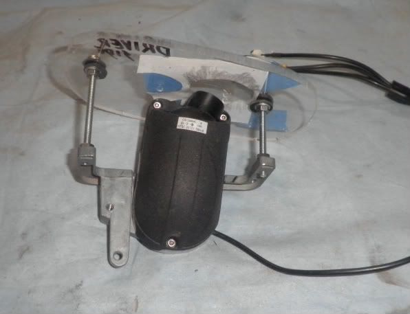
This weekend was rather wet, so the cameras were mounted in the side mirrors. The mirrors are RX-7s and were motorized, but the motors were no good and were disposed of. The framework for the motors made a place for the cameras to be mounted. Dremel tool, drill, and tap and they were done(figuring out their location took longer than to fix them up). Here are some of the construction shots.

The mirrors themselves will be mounted in a fixed position in front of the camera. The cameras were placed as close to the front as possible.

They have a side range of about 30 degrees in all directions. With the camera looking off to one side an aperture in the reflective surface is needed, so an ellipse was made by using a circle template from the web and elongating it on screen and printing it out. Several sizes were cut out til one that seemed to fit the best was chosen. When finished the surface of the mirror will be reflective with a clear section for the camera to see out.
Sort of like this.

Now to get them out to the painters.
Bill
The mirrors themselves will be mounted in a fixed position in front of the camera. The cameras were placed as close to the front as possible.
They have a side range of about 30 degrees in all directions. With the camera looking off to one side an aperture in the reflective surface is needed, so an ellipse was made by using a circle template from the web and elongating it on screen and printing it out. Several sizes were cut out til one that seemed to fit the best was chosen. When finished the surface of the mirror will be reflective with a clear section for the camera to see out.
Sort of like this.
Now to get them out to the painters.
Bill
Have been out of town for the last week. Boy did I need it. Was an Anesthesia meeting but still got lots of time in the sun and water. If you guys want a nice place to visit I would highly recommend it. It was the Sandals Resort, Beaches on Turks and Caicos island in the Caribbean. It is expensive but it is all inclusive. That means you pay nothing once you are there. Np tipping, 16 restaurants, about 7 pools, most with swim up bars. You eat all you want, what you want when you want and the same goes for liquor. Though you do have to put up with their bar brands. I think I had more rum there than I had in the last 10 years. They do have butler service in the Italian village, white gloves and all. The food is top notch. They had lots of entertainment for families and adults. I should know, I got pulled into the Rock and Roll legends concert. We won't talk about the short dresses and wigs. Next trip I will have learned SCUBA diving and take in the 2 dives a day offered. Oh yeah, that's included. The only things you pay for are the tourist things like T shirts etc. and they are expensive-$26. I never carried cash or a billfold the entire time there.
Now back to the build. I completed the mounting of the cameras and tried it out with some Lexan I had laying around, and here is how the foot print will work out.

The image has only slight edges of the cut out. The screws are out of view. Once mounted on the windows the "window" will be adjusted as needed before going to the mirror people. With the 120 lens I don't think it will need any modification. Next comes the central surface mount camera and its enclosure on the spyder. I am working on the panel line up. The rear hatch is slowly finding it way back into place with the help of the sun. Trimming and latches will continue til ready for paint.
Bill
Now back to the build. I completed the mounting of the cameras and tried it out with some Lexan I had laying around, and here is how the foot print will work out.
The image has only slight edges of the cut out. The screws are out of view. Once mounted on the windows the "window" will be adjusted as needed before going to the mirror people. With the 120 lens I don't think it will need any modification. Next comes the central surface mount camera and its enclosure on the spyder. I am working on the panel line up. The rear hatch is slowly finding it way back into place with the help of the sun. Trimming and latches will continue til ready for paint.
Bill
Took the car out to get the final tuneup. Engine running fairly decent,but still persist in a high idle. Can tell the throttle bodies are not in syncdue to exhaust glowing at higher RPMs on only a few cylkinders.
With the tune up the engine has settled down and starts effortlessly. Maintains a nice idle and responds to the throttle very well. Put the car on the dyno to get some numbers, only to find the clutch would not release. An attempt to lenghten the adjustment screw by removing the lock nut was not going to work because the no.6 exhaust was blocking its removal. The collector on the passenger side was removed, and the offending exhaust tube was loosened and was able to remove the screw and nut. After reinstalling all with the lock nut out, the lenght was still not enough to get the trans in gear with the motor running, so the car was taken off and loaded onto the trailer. My Porshe mechanic and I measured the distance that the arm traveled and found it to be about 2 mm. It was then we noticed the stop on the pedal was in the full out position. After removing it totaly, we found the movement to be only 7 mm. There was considerable distance from the adjustment screw to the actuator arm. The cross bar under the exhaust sits barely over the top of the actator arm. So the cross bar will have to be loosened up to get it off and turn the arm one or two positions. The numbers for setting the actuator arm, for the throwout bearing is a 2 mm gap in the arm to keep the bearing off the pressureplate(mine was about 1/2"). The travel of the actuator arm is supposed to be 13 mm. So I will remove the exhaust and cross bar and set the arms closer together. This should straighten things out.
While at the dyno shop I got the fabricators next door to fab up some canards for the front fenders. These are the same guys that made my A/C mount.

They made a backing plate for the inside of the fender to give it some support. Will post some more pics when mounted.
If I can get some uninterrupted time this weekend, I might be able to squeeze in the first trial run of the car.
Bill
With the tune up the engine has settled down and starts effortlessly. Maintains a nice idle and responds to the throttle very well. Put the car on the dyno to get some numbers, only to find the clutch would not release. An attempt to lenghten the adjustment screw by removing the lock nut was not going to work because the no.6 exhaust was blocking its removal. The collector on the passenger side was removed, and the offending exhaust tube was loosened and was able to remove the screw and nut. After reinstalling all with the lock nut out, the lenght was still not enough to get the trans in gear with the motor running, so the car was taken off and loaded onto the trailer. My Porshe mechanic and I measured the distance that the arm traveled and found it to be about 2 mm. It was then we noticed the stop on the pedal was in the full out position. After removing it totaly, we found the movement to be only 7 mm. There was considerable distance from the adjustment screw to the actuator arm. The cross bar under the exhaust sits barely over the top of the actator arm. So the cross bar will have to be loosened up to get it off and turn the arm one or two positions. The numbers for setting the actuator arm, for the throwout bearing is a 2 mm gap in the arm to keep the bearing off the pressureplate(mine was about 1/2"). The travel of the actuator arm is supposed to be 13 mm. So I will remove the exhaust and cross bar and set the arms closer together. This should straighten things out.
While at the dyno shop I got the fabricators next door to fab up some canards for the front fenders. These are the same guys that made my A/C mount.
They made a backing plate for the inside of the fender to give it some support. Will post some more pics when mounted.
If I can get some uninterrupted time this weekend, I might be able to squeeze in the first trial run of the car.
Bill
 epper:
Similar threads
- Replies
- 42
- Views
- 5K