

- Forums
- GT40 Replica Manufacturers' Corner
- RCR Forum - RCR40/SLC/917/Superlite Aero
- The SLC Clubhouse
You are using an out of date browser. It may not display this or other websites correctly.
You should upgrade or use an alternative browser.
You should upgrade or use an alternative browser.
Ken's SLC build thread
- Thread starter KENS80V
- Start date
Ken Roberts
Supporter
Are those lights still Hella brand?
Yes all four lamps are Hella. The Bi halogen headlights are heavy though and will need to be installed carefully.
The side lamps are from BMW (Mini Cooper up to 2006 I believe)
I really like the fender lip lights....I have some similar I want to install in the shop Apex
Ken Roberts
Supporter
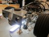
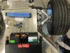
Here is a picture of the crude jig we made to locate the muffler tips in the correct location with the body work removed.
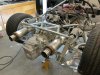
Here is the end result with the exhaust system tack welded together. The mufflers are 5" in diam. I first tried 6" mufflers but found the clearance was nil in several places.
Here is the end result with the exhaust system tack welded together. The mufflers are 5" in diam. I first tried 6" mufflers but found the clearance was nil in several places.
Attachments
Last edited:
Ken Roberts
Supporter
Ken, the "finished" mufflers look like they're sitting a hair lower than the jig pics? You're correct about the 6" mufflers - mine are right up against the upper x-brace .. tight fit.
Great observation Mike! Once we pulled the jig away the mufflers dropped a bit due to the fact the clamps were loose. We had about 3/16' clearance from the x brace and 3/16" clearance from the axle heat shields.
Ken Roberts
Supporter
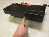
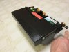
Here are some observations to do with the supplied AC unit.
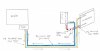
The first picture shows me pointing to where the outlets were installed on the standard "mini slimline" sold by Vintage Air. Ours are left blank due to the fact the air must leave straight up.
The first picture shows me pointing to where the outlets were installed on the standard "mini slimline" sold by Vintage Air. Ours are left blank due to the fact the air must leave straight up.
Attachments
Last edited:
Ken Roberts
Supporter
Exactly...thanks Ken...
Ken Roberts
Supporter
Ken Roberts
Supporter
Ken Roberts
Supporter
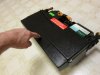
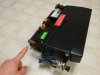
Here is a picture of the left side. I'm pointing to the heatercore inlet and outlets. The knob (to the right) is for the freeze up adjustment. The probe mounts in the top and enters at the point where freeze ups might happen.
As you can see from all the pictures this is a very simple AC unit. There are no other doors/outlets for defrost or footwell. If you want to have the most room for passenger comfort (their feet comfort anyway) this is as small as they get.
As you can see from all the pictures this is a very simple AC unit. There are no other doors/outlets for defrost or footwell. If you want to have the most room for passenger comfort (their feet comfort anyway) this is as small as they get.
Attachments
Last edited:
Ken Roberts
Supporter
Hey Ken...Thanks for the great pics. I haven't really unpacked mine yet...
Which hose attaches to that "problem" fitting? Can it be swapped for a 90?
The high pressure #6 hose that goes to the drier and then on to the lower fitting on the condenser
Ken it is a very tight fit even with just the A/C and no heater core. I couldn,t get mine to fit till I moved the A/C coil tubes to the drivers side and that left me with nothing on the passingers side then it fit but it was still snug. Ben was having issues with his too, he has the same set up as you. hope you can get this in with out to much messing around I am thinking there maybe some mods required by a rad shop to add some length on and turn the tubes so they face backwards / towards the nose.
Ken Roberts
Supporter
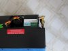
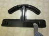
This picture shows the black fiberglass box (gets bonded to the tub top) that is supplied that transfers the conditioned air to the defrost outlets in the dash and the front outlets. My foot is touching the section of the fiberglass where the AC unit mounts below the aluminum panel. This is the area that has the series of holes in it.
Attachments
Last edited:
Ken Roberts
Supporter
Ken it is a very tight fit even with just the A/C and no heater core. I couldn,t get mine to fit till I moved the A/C coil tubes to the drivers side and that left me with nothing on the passingers side then it fit but it was still snug. Ben was having issues with his too, he has the same set up as you. hope you can get this in with out to much messing around I am thinking there maybe some mods required by a rad shop to add some length on and turn the tubes so they face backwards / towards the nose.
I liked your idea Grant. You don't have the heater core in your mini slimline (cool only) so it was fairly easy to flip it over to the otherside. We can't do this though due to the heatercore being located on the otherside.
It is important to move the AC unit as far to the center as possible to minimize this hose hookup interference we are talking about.
Ken Roberts
Supporter

Ken Roberts
Supporter
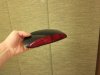
Here is a picture of the center mounted brake light I'm going to try and install. It will be on the roof of the spider as far back as I can mount it (just above the rear window). It's from a 2001 Taurus station wagon.
Our laws here for street registration say that the minimum mounting height must be 34".
Our laws here for street registration say that the minimum mounting height must be 34".
Attachments
Last edited:
Ken Roberts
Supporter
Similar threads
- Replies
- 40
- Views
- 3K