Mark's GT-R Build

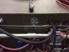
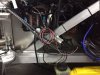
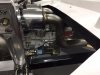
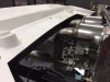
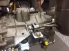
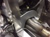
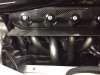
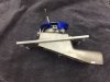
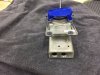
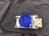
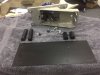
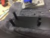
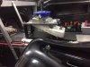
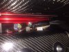
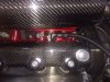
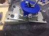
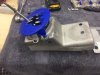
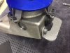
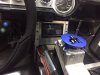
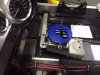
I have all of the Infinity cells and wiring harnesses attached to the Infinity components. The fire wall connector was certainly fun to install. The space getting to the forward wall in the foot well is REALLY LIMITED.

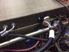
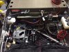
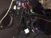
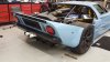
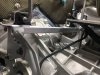
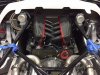
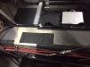
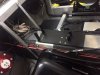
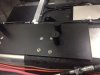
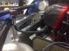
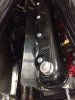
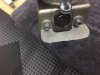
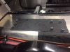
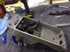
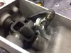
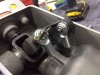
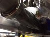
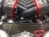
They say that the only way to eat an elephant is one bite at a time. I guess the same holds true for wiring this car...... One wire at a time. I have the lines all run in their general direction, have the brake pedal switch wire attached and the starter solenoid wired. There is a long way to go.
 

Attachments

  • IMG_4666.JPG
    IMG_4666.JPG
    56.9 KB · Views: 329
  • IMG_4667.JPG
    IMG_4667.JPG
    59.1 KB · Views: 295
  • IMG_4668.JPG
    IMG_4668.JPG
    63.9 KB · Views: 387
  • IMG_4670.JPG
    IMG_4670.JPG
    43.1 KB · Views: 322
  • IMG_4672.JPG
    IMG_4672.JPG
    51 KB · Views: 338
I just received the shifter assembly from Audi. I am sure the shifter that comes with the kit can work just fine, but I kind of view it as a "Hot Rod" shifter and I feel I am building a Sports Car.

I know the Audi shifter is costly, but it feels like quality. First of all, the gated feature looks great. The shifter movement is very smooth and gears 1 and 2 have spring resistance, as well as gears 5 and 6, so you will always know what gear you are going into. There are YouTube videos that Audi R8 owners have put up just to let people see and hear the shifting in their cars, they are that impressed with it.

I look forward to getting it in the car, which is not going to be easy, as you will see.
 

Attachments

  • IMG_4682.JPG
    IMG_4682.JPG
    39.1 KB · Views: 415
  • IMG_4681.JPG
    IMG_4681.JPG
    24.8 KB · Views: 460
Mark I can attest to the delightful gated shifter in the Audi as my R8 is sublime and the sound of the click - clack going from gear to gear is truly enjoyable. Keep us posted. Very nice piece you've bought.
 
Thanks for your comment, Jimmy. The R8 looks like an awesome car. It seems like the gated shifter is really a feature in the R8, so I wanted it in the GT-R.
 
I returned from traveling for six weeks only to find our Island is in the sights of hurricane Irma. Got back to find Marco Island has a lot of trees and branches down, some roof tiles missing, but minimal structural damage to the buildings on the island. Now have power, water and internet.

Went up to the shop and all is well. Got my exhaust tubing finished. The ends is just "tack" welded to decide on the final location. I am trying to decide if I should add the rear bumper or not. Ron has a great one in development and I will need to relocate the exhaust tips if I put a bumper on.

I am looking forward to getting back in the shop next week and working on the Audi shifter install, wiring and getting the interior tub in place.
 

Attachments

  • IMG_4831.JPG
    IMG_4831.JPG
    37.6 KB · Views: 436
  • IMG_4830.JPG
    IMG_4830.JPG
    38.5 KB · Views: 377
  • IMG_4829.JPG
    IMG_4829.JPG
    37.3 KB · Views: 366
H: I tend to agree with you. There is a lot of wire mesh showing without a bumper and it does add a finished look. Thanks for your comment.
 
I just wanted to post some of the details on the exhaust hangers and the modified motor mounts. I wanted to have the exhaust system attached to the motor/transaxle only, to reduce the risk of vibration compromising things if the exhaust was also attached to the chassis. The welds on the tips are not complete because of the need to get the bumper on to get the final measurements.

The way we made the headers required a modification in the engine mounts, so the new mount is done and worked out great.
 

Attachments

  • IMG_4833.JPG
    IMG_4833.JPG
    47.8 KB · Views: 342
  • IMG_4834.JPG
    IMG_4834.JPG
    55.2 KB · Views: 303
  • IMG_4836.JPG
    IMG_4836.JPG
    38 KB · Views: 326
  • IMG_4837.JPG
    IMG_4837.JPG
    33.2 KB · Views: 297
  • IMG_4839.JPG
    IMG_4839.JPG
    44.1 KB · Views: 334
You may recall that I fabricated some brushed stainless heat deflectors to keep the heat that comes off the headers from damaging the carbon fiber valve covers. Today I added the Lava Shield to the header side of the stainless. This is the most heat reflective material that I could find and have used it throughout the engine bay.
 

Attachments

  • IMG_4626.JPG
    IMG_4626.JPG
    49.5 KB · Views: 313
  • IMG_4629.JPG
    IMG_4629.JPG
    58.4 KB · Views: 325
  • IMG_4853.JPG
    IMG_4853.JPG
    62.6 KB · Views: 289
The Audi R8 Shifter assembly is a rather odd shape to mount to the flat console area in the GT-R. Fortunately I drilled and tapped holes for mounting the supplied shifter. Dean's build well demonstrates the difficulty in mounting to the console after the gas tank is installed.

Using a steel plate and the original holes from the supplied shifter, I made some "pillars" to get the Audi Shifter solid and stable.
 

Attachments

  • IMG_4840.JPG
    IMG_4840.JPG
    59.5 KB · Views: 268
  • IMG_4842.JPG
    IMG_4842.JPG
    70.3 KB · Views: 249
  • IMG_4841.JPG
    IMG_4841.JPG
    62.5 KB · Views: 235
  • IMG_4848.JPG
    IMG_4848.JPG
    38.1 KB · Views: 252
  • IMG_4845.JPG
    IMG_4845.JPG
    63 KB · Views: 262
  • IMG_4850.JPG
    IMG_4850.JPG
    46.8 KB · Views: 230
  • IMG_4849.JPG
    IMG_4849.JPG
    53.8 KB · Views: 255
  • IMG_4852.JPG
    IMG_4852.JPG
    45.2 KB · Views: 319
After the initial try in, I painted up the fabricated pieces and proceeded to get it mounted. Audi uses rubber in their mounting, so the two holes I added at the back of the assembly had provision for rubber mounting.

In mounting the plate, I hade to allow for the heads of the bolts on the underside of the mounting plate, so I used some metal spacers to elevate the mounting plate enough to provide clearance for the bole heads.
 

Attachments

  • IMG_4854.JPG
    IMG_4854.JPG
    54.5 KB · Views: 291
  • IMG_4858.JPG
    IMG_4858.JPG
    55 KB · Views: 257
  • IMG_4859.JPG
    IMG_4859.JPG
    42 KB · Views: 311
  • IMG_4861.JPG
    IMG_4861.JPG
    36.4 KB · Views: 273
  • IMG_4863.JPG
    IMG_4863.JPG
    43.9 KB · Views: 320
This mounting allows for the shifter knob to be in almost the same location as the supplied shifter. I will need to customize the fiberglass console to accommodate the Audi pieces. The feel of the new shifter is really worth the cost and the trouble.
 
While I am waiting for some electrical parts (Weather Pak Connectors), I decided to start on getting the body prepped. It is playing for keeps when you start cutting on the body. I started with the rear end openings.
 

Attachments

  • IMG_4864.JPG
    IMG_4864.JPG
    47.1 KB · Views: 449
My engine came with some brass fittings used to ventilate the valve covers, which was not going to fit in the cosmetics of the engine that I am looking for, as the last picture shows. I used 6AN fittings on the valve covers and on both sides of the intake. I went from the small air filter mounted on the chassis support tube to the driver side valve cover, then from the passenger valve cover to both sides of the intake manifold. I am having a "restrictor" made to add to the system to limit the vacuum that the intake can create.
 

Attachments

  • IMG_4870.JPG
    IMG_4870.JPG
    50.9 KB · Views: 331
  • IMG_4871.JPG
    IMG_4871.JPG
    62 KB · Views: 259
  • IMG_4868.JPG
    IMG_4868.JPG
    53.4 KB · Views: 229
  • IMG_4869.JPG
    IMG_4869.JPG
    66.4 KB · Views: 220
  • IMG_4620.JPG
    IMG_4620.JPG
    47.8 KB · Views: 254
Not quite sure I understand how you are venting the crank case. At a glance, it seems like you have vented it (the reason for the filters) and plumbed it into the intake. Is that correct?
 
Yes, I am using the intake as a vacuum (with a pinhole resistor plate in the 6AN line) and drawing air from the filter to one valve cover, then from the other valve cover into a "Y" in the AN line, then to both sides of the intake.
 
I mounted the Audi shifter assembly in the ideal place for the shift knob position, but when I was seated in the mocked up interior, the plate used by Audi for mounting was blocking some of the monitor on the entertainment center.

That being the case, I revisited the mounting and removed the Audi plate and removed only the portion I needed for a mounting with a smaller foot print. You can see the outline on the plate after it was removed.

I used spacers between the original console surface and the base for the pillars to allow for space for the bolt heads holding the pillars.

The view of the monitor is not perfect, but it is much improved. I will make the fiberglass console tightly adapted to the Audi shifter outline, keeping access to the entertainment center as much as possible.
 

Attachments

  • IMG_4872.JPG
    IMG_4872.JPG
    36.4 KB · Views: 247
  • IMG_4877.JPG
    IMG_4877.JPG
    52.2 KB · Views: 180
  • IMG_4878.JPG
    IMG_4878.JPG
    58.1 KB · Views: 189
  • IMG_4879.JPG
    IMG_4879.JPG
    68.7 KB · Views: 208
  • IMG_4880.JPG
    IMG_4880.JPG
    69.3 KB · Views: 238
  • IMG_4881.JPG
    IMG_4881.JPG
    50.7 KB · Views: 185
  • IMG_4882.JPG
    IMG_4882.JPG
    43.4 KB · Views: 178
  • IMG_4884.JPG
    IMG_4884.JPG
    38.7 KB · Views: 201
  • IMG_4885.JPG
    IMG_4885.JPG
    41.7 KB · Views: 213
  • IMG_4886.JPG
    IMG_4886.JPG
    43.2 KB · Views: 231
  • IMG_4887.JPG
    IMG_4887.JPG
    43.7 KB · Views: 209
Modifying the cable attachments to work with the supplied cables takes a little bit of work. I am using the technique recommended by Allan, grinding off the ball on the Audi shifter, then using Heim joints to connect to the cables. It looks really simple, and it is, except for the need to drill into the hardened steel shafts in the Audi to use cotter pins to lock on the joints. The holes need to be small to keep the structure of the shaft and the metal is HARD!!! Broken drill bit galore and I have one hole done, and the other half way. I will pick it up again tomorrow after I get more drill bits.
 

Attachments

  • IMG_4888.JPG
    IMG_4888.JPG
    58.4 KB · Views: 229
  • IMG_4889.JPG
    IMG_4889.JPG
    45.5 KB · Views: 270
  • IMG_4890.JPG
    IMG_4890.JPG
    47.9 KB · Views: 246
Back
Top