McCopy mk 5

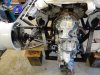
Mike, sorry but no, mine is the 4 ltr version and as Jacmac has commented, there are significant variations as the sump versions are in two parts. Changing versions is quite involved.
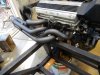
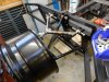
Jac, are those manual gearboxes under that bench?
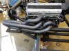
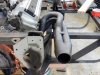
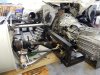
My runners averaged 28inches plus whats in the heads.
Cheers
 
Exhausting business this, completed the off side now and will go back and redo the left hand back pipe as I can make it tidier and a bit lower to give good clearance under the rear deck.
I only hope that my shocks and springs clear underneath the pipe.
Looking forward to Friday as the Dodge Hell Cat will be cleared for delivery, its been long awaited as the boot is full of shocks,springs and a gearbox....not looking forward to the customs fees! but hey its all here now.
Cheers
 

Attachments

  • DSCN1850.jpg
    DSCN1850.jpg
    164.7 KB · Views: 407
  • DSCN1851.jpg
    DSCN1851.jpg
    167.6 KB · Views: 387
  • DSCN1849.jpg
    DSCN1849.jpg
    154.7 KB · Views: 362
Nice set of pipes there young fella, having built the set for mine I know how much work goes into them well done sir.
btw. I got your E Mail but havnt got around to replying sorry mate , also havnt sent those adapters either now that I think about it, boy have I been slack, ill get onto it this week promise.

cheers John
 
Front suspension getting mocked up, will end up with a good angle on the shocks. The Hell cat got released on Friday and after looking at the front brakes, mine look positively puny, May have to be a rethink.
No parts yet as they were unpacked from the boot and are being assessed!
The new car must have some sting as one of his other cars is a BMW 735 ? Twin turbo V8 that just flies.
Cheers
 

Attachments

  • DSCN1864.jpg
    DSCN1864.jpg
    182.2 KB · Views: 398
  • DSCN1857.jpg
    DSCN1857.jpg
    211.5 KB · Views: 357
  • DSCN1860.jpg
    DSCN1860.jpg
    193.1 KB · Views: 362
  • DSCN1861.jpg
    DSCN1861.jpg
    286.5 KB · Views: 358
Its like Christmas, finally got my bits from Summit and my gearbox. My Bro managed to get an 012 same ? similar to what I have in the other car so its off getting the adapter machined, already got the 1uz side done so should have it back in a few days. Its supposed to be a factory reconditioned one but it looks new to me. Very happy. Lucky the car had a big boot.
Shocks, springs, rod ends, steering wheel mean that work can start in earnest.
Cheers
 
Progress
Front shocks all set up with top mount height adjustable for the moment. Spent most of Wed, trying to attache bottom shock mount closer in with the bottom shock mount under the wishbone. It did not look good and I was chasing strength so chopped it off and mounted it on top of the bottom ball joint bolt pattern. Whilst this put slightly more angle on the shock, its still more than acceptable and much stronger. Also picked up the Toyota 1uz / Audi adaptor plate which will again run the ring gear rebated into the back of the plate. Will see what it fits like over the next few days and get the rear trans mounts and chassis completed.
Cheers
 

Attachments

  • DSCN1864.jpg
    DSCN1864.jpg
    182.2 KB · Views: 360
  • DSCN1876.jpg
    DSCN1876.jpg
    186.1 KB · Views: 403
  • DSCN1878.jpg
    DSCN1878.jpg
    133 KB · Views: 360
High
Some progress to report.
Transaxel in, front suspension mocked up, rear mocked up, new front discs (BMW Cooper 295mm vented drilled and slotted) and Willwood calipers.
Time to get the certifier in for a look.... not happy with my rear toe rod ends being side loaded by the shock position on the wishbone acting as a bending moment and I do need adjustment for toe in / out adjustments.
The left hand axel is standard length with the adaptor and the right hand one needs a wider spacer.
Any ideas on the shock mounting issue?
My thoughts were to mount the shock directly onto the upright and then the load is transfered thru that to the wheel and ground. The rod ends then only maintain toe and position. I need to buy the the LOW VOLUME VEHICAL MANUAL before I get to carried away any further. All the `comments` were fine as its aimed at a safe final outcome.
Had a good think about how best to make my rear clevis and turned my lathe into a mill....remembered real quick to mill against the cutter direction after a massive `grab`.
Now for a break and some rethinking as we need to navigate thru LVVTA and race car rules as we have a bit in each camp.
Cheers
 

Attachments

  • DSCN1952.jpg
    DSCN1952.jpg
    177.5 KB · Views: 403
  • DSCN1951.jpg
    DSCN1951.jpg
    190.2 KB · Views: 389
  • DSCN1948.jpg
    DSCN1948.jpg
    169.5 KB · Views: 334
  • DSCN1953.jpg
    DSCN1953.jpg
    188.1 KB · Views: 389
  • DSCN1956.jpg
    DSCN1956.jpg
    186.1 KB · Views: 371
  • DSCN1959.jpg
    DSCN1959.jpg
    117.9 KB · Views: 390
two ways to do it Russ, on the Brabham I did it the same as you have now, but used a 5/8 rod end for the extra strength, on the McLaren I've opted to go direct to the upright, just to keep every one happy.
what axle did you use and what length are they, ?

cheers John
 

Terry Oxandale

Skinny Man
With the steel uprights, you could drill a horizontal hole all the way through the upright's lower leg, just above the rod-end hole, insert and weld a tube into the holes (inner and outer weld), tap it for a bolt, and then bracket up a couple of plates to hold the shock up over the top of the rod end (like many OEM shock mounts for this type of upright). Probably would require a longer shock though, with increased angle.
 
John
The Holden SS axels are approx 480mm long.
For LVVT road certification they will not let you use a rod end in a bending moment so I have re jigged the upright to mount the shock direct, bit of a pain as the axel is in the way...never mind it clears the shock now and is substantial so should be ok.
There is 485 pages in the LVVT book so a bit of reading.
Cheers
 

Attachments

  • DSCN1969.jpg
    DSCN1969.jpg
    181.2 KB · Views: 434
  • DSCN1973.jpg
    DSCN1973.jpg
    174.5 KB · Views: 400
Hey Russell, It's looking good is there a reason you cant just spread the inner end of the lower arms, rather than having to have them bent. And i agree the construction manual is dawnting there seems to be more you cant do compared to what you can. And everytime you reread it you find more got yaahs lol.
 
Graeme, the lower arms are single point attachment to the chassis and double on the uprights.
Cheers
Going to have them crack tested tomorrow...that should be interesting.
 
So over there they won't allow you. To add the load of the shock/spring to the A arm? Seems like a pretty normal set up. That's the way I have mine I know.
 
It is common sense when you think about it.. to place the coil over lower attach point on the w/bone would place those corner loads on the threads of the rose/heim joint in a manner that it is not designed for and prone to failure in the threaded area. Plus by mounting on the upright you get full wheel rate on the spring/shock whereas on the w/bone it gets a % of that. So its a win/win.
 
TIG WELDING
Not wishing to tell you all how to suck eggs....I have been on a self induced learning curve on how to TIG weld, discovered all sorts of tricks but have just found the best device yet which has given a 100% weld quality improvement and ease of use. I have just purchased a gas lens that creates a vortex around the electrode giving better control of the gas `window`.
I have just welded up my new brake pedal and really pleased with the outcome, I would never have been able to weld this fine before.
The rules for road registration state 8mm thick steel but make no mention of section!
This one will certainly fit the bill.
Also just had my rear uprights that are steel fabrications crack tested and they have come thru with flying colours, now to make my second set of wishbones.
Cheers
 

Attachments

  • DSCN2028.jpg
    DSCN2028.jpg
    132.4 KB · Views: 394
  • DSCN2033.jpg
    DSCN2033.jpg
    127.8 KB · Views: 368
Hi Russ whats the pedal ratio, looks about 6-1, they definitely look the part, youll need bloody big legs to bend those.
cheers john
 
Just over 5 to 1 John, In the previous pedal I did not have a `wobbly` balance bar so corrected it with a self aligning bearing in the pivot so all was not in vain.
Cheers.
Russell
 
Back
Top