
great stuff Jim.
so many details to take in!!!
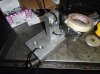
what size collet chuck are you running ER32 or ER40?
Ryan
From memory I think its an ER32, but its been a while, the mill is a Hafco HM50 from hare and forbes.

great stuff Jim.
so many details to take in!!!
what size collet chuck are you running ER32 or ER40?
Ryan
Will you be welding a ring into the outer to bolt the centre to ??
Hey Chris
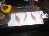
knowing Jim, he probably free hand the radius and got all four within 0.005" of each other :stunned:
Clayton
Thanks Jim. Sounds similar to my mill. Only had it a week or two and love it. Still need to get some more tooling though and a collet chuck is on the list.
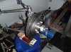
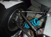
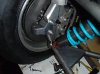
Jim what is the sensor for in the back of your front upright hub? Speedometer or traction control?
Maybe I'm just dense. But a 206 what? I've gone through your thread & it's a quite impressive build. But I don't know what kind of car it is except a mid-engine?
ok yes a very pretty car. What are you going to do about a body? Build your own or know where to buy one? Hope all works out & fits right. Great looking job on the tub.


")