Scratch-built aluminum inboard v-drive boat

The steering and it's components "C".

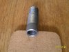
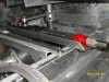
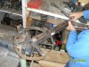
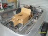
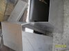
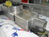
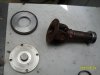
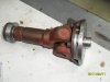
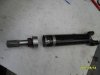
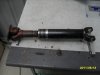
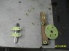
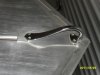
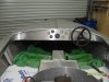
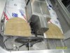
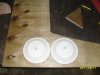
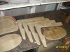
To mount the casing end a standard 7/8" - 14 unf bolt 3" long was modified. Pic c10. My method to align the components was to use a threaded rod with circular rings that fits into all the holes. These rings was just hex nuts turned down to suite. Pic c20 and c30.

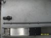
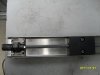
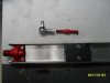
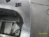
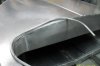
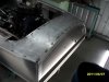
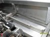
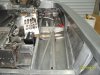
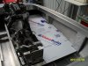
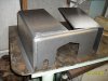
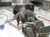
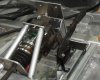
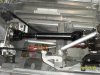
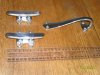
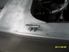
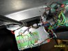
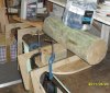
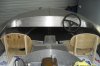
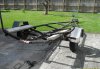
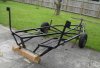
Pic c50 shows the casing end mounted with the link bar activating the tiller arm, which is bolted onto a boss which is bolted onto the rudder post. A bearing block supports the rudder post above the tiller arm boss.

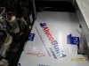
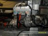
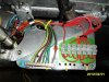
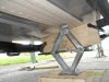
Just sticking out the bronze water gland is visible. A nylon insulator was used to help prevent galvanic action.

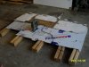
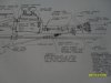
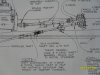
A large drawing was made to determine the geometry to ensure there is equal rudder movement from left to right.

I have difficulty uploading pics. This is the message:

" Your submission could not be processed because a security token was missing."

To get past this token message I had to up load one pic at a time.
 

Attachments

  • steer c10.jpg
    steer c10.jpg
    171.6 KB · Views: 260
  • steer c20.jpg
    steer c20.jpg
    105.6 KB · Views: 251
  • steer c30.jpg
    steer c30.jpg
    112.9 KB · Views: 242
  • steer c40.jpg
    steer c40.jpg
    103.2 KB · Views: 256
  • steer c50.jpg
    steer c50.jpg
    171.8 KB · Views: 265
Some finishing touches to the hull.


There was a bit of a gap where the deck, gunwales and dash meet. I made a quick roll former to bend round bar to the same diameter as the curve of the dash. If you ever do this, keep in mind there may be a reasonable amount of spring back, therefor the former diameter is smaller than the required bend.

I bend a far longer piece than what is needed. Now it is easy to cut off just the correct length to fit. A little more tricky was to cut away a piece of the infill radius between dash and gunwale so that the bend round bar will fit just nice. Afterwards the bend was welded in.
 

Attachments

  • 80-10.jpg
    80-10.jpg
    115 KB · Views: 257
  • 80-30.jpg
    80-30.jpg
    209 KB · Views: 265
  • 80-40.jpg
    80-40.jpg
    105.5 KB · Views: 288
  • 80-50.jpg
    80-50.jpg
    79.4 KB · Views: 256
  • 80-60.jpg
    80-60.jpg
    98.3 KB · Views: 251
More finishing touches to the hull.


Trim extrusions was also welded over all exterior weld joints. All weld spots was later sanded flat. Can you see the window reflection on the deck?
 

Attachments

  • 80-70.jpg
    80-70.jpg
    91.9 KB · Views: 303
  • 80-81.jpg
    80-81.jpg
    121.7 KB · Views: 349
  • 80-90.jpg
    80-90.jpg
    220.2 KB · Views: 392

Randy V

Moderator-Admin
Staff member
Admin
Lifetime Supporter
Very nice work! I wish I was that accomplished in welding aluminum! :thumbsup:
 
Its a credit to you Zollis.
I can see a ton of work in that project.

The sides did you get them off a roll, it is 1 piece to the water line by the look.
Did you put a compound on them to stop them tin canning.

Jim
 
Randy , thank you for the compliment, although there is always room for improvement.

Jim, yes a ton of work. If I worked in fast food selling burgers each hour I have spend on the project I could have bought a boat/car brand new. What would I have learned then ?? Now I have the satisfaction to know this is the ONLY one in the world, like this.

Only the rear transom (2nd pic post 23) was put thru a roller before fitting up. Yes tin canning is the one to watch out for. Before construction started when I had the wire frame work (post #4) I investigated the phenomena. I used 0.016 " ali sheets cut to shape and curved around the wire. I adjusted the overall shape of the boat to prevent tin canning. All plates has curvature in them. From a distance ( pic 3 post#23) the sheets may look flat but as you can see on today's pics there is curvature.


THE FLOOR.

Under the floor there are angled supports. To get the correct height of the rear support located at the outer edge took some thinking. I took a long straight edge ( pic 2) to pick-up the front and middle support heights. Easy once figured out.

I wanted the floor to be as close to the sides as possible. I took cardboard pieces and plenty of tape to establish the shape. This template was then traced onto the floor material which is a composite consisting of polyethylene with ali outer skins. 4 mm thick. The caravan industry uses these a lot.
 

Attachments

  • 90-10.jpg
    90-10.jpg
    136.1 KB · Views: 309
  • 90-20.jpg
    90-20.jpg
    171.3 KB · Views: 296
  • 90-30.jpg
    90-30.jpg
    154.5 KB · Views: 276
  • 90-40.jpg
    90-40.jpg
    137.9 KB · Views: 298
  • 90-50.jpg
    90-50.jpg
    106.6 KB · Views: 248
Merry Christmas to all of you.


The inside covers.

The main purpose of the covers are to protect people on board from moving / rotating machinery. They have to be strong enough to support a person if he sit or stand on them. I used 2.5 mm thick grade 5052 ali.

First of all cardboard templates were cut and taped into position to see how it looks. From this measurements were taken and transferred to the ali. I used a new subcontractor to bend the ali in his brake-press. To cut a long story short I could NOT use the parts because the bend radius on the corners were to sharp. See pic #2. What a waste of time and material !! So , back to the guy I know but pay a little more. Nice big radius now.

To ensure that the internal supports had clearance around the fixed mechanical components they were made first before welding to the covers. See pic # 4 .

The covers are light and can easily be put on or removed by one person.
 

Attachments

  • cover 10.jpg
    cover 10.jpg
    168.2 KB · Views: 270
  • cover 20.jpg
    cover 20.jpg
    120.7 KB · Views: 248
  • cover 30.jpg
    cover 30.jpg
    159.8 KB · Views: 252
  • cover 40.jpg
    cover 40.jpg
    158.5 KB · Views: 286
  • cover 50.jpg
    cover 50.jpg
    129.4 KB · Views: 256
  • cover 60.jpg
    cover 60.jpg
    136.4 KB · Views: 249
First start up.

There are a few things to get in order before the first start up can start.

Water. Three places where it is required. Obviously inside the closed loop system of the engine. Secondly a garden water hose pipe feed that goes in under the boat where the raw water pick up is and thirdly another garden water hose to lubricate the prop shaft where it turns inside the water lube bearing which is pressed into the under water strut.

Plus the basics like fuel , battery, oil etc.

Starts fine. Check oil pressure, water temperature, yep all fine. Now let me rev it up a bit.


SURPRISE.


For the first time I saw something that I think very few people has ever seen. A CV boot as BIG as the size of a football.------ and then lets go.

Grease , Grease everywhere. Sorry no pics, I was toooo startled.

Why did this happen????

The revolutions were to high and centrifugal force came in for a little play. The standard application for this CV boot is on the half shaft from a front wheel drive sedan. The revolutions the shaft under goes is far less because the differential gearing is doing it's part. Now here I was spinning this shaft at engine revs, say about 5000 rpm.

Just one thing to do now.!! Make a new drive shaft and use the existing holes for the drive bolts. An adapter was made and a few hours of work was spend on a conventional set-up. This works fine now.

The eagle eyed guy would have noticed that the engine is installed at a tilt. The reason is for the front and rear universal joints to work at the same angle to help prevent vibration.


.
 

Attachments

  • first test run 20.jpg
    first test run 20.jpg
    179.6 KB · Views: 1,573
  • new drive 10.jpg
    new drive 10.jpg
    131.4 KB · Views: 245
  • new drive 30.jpg
    new drive 30.jpg
    114.5 KB · Views: 273
  • new drive 40.jpg
    new drive 40.jpg
    107.7 KB · Views: 238
  • new drive 50.jpg
    new drive 50.jpg
    105.8 KB · Views: 254
  • new drive 60.jpg
    new drive 60.jpg
    160.8 KB · Views: 259
You might want to check out your 'new' driveshaft with a couple of degree wheels attached @ the flanges of the shaft, I think you will find you have doubled the u-joint induced speed change by using the angles as shown [ not cancelled it out- you probably wont notice it in an unloaded condition, but once in water with prop load it should show up ]...ie shafts from motor & VW case should be parallel in vertical plane.., CV joints from late model Falcon or Commodore ( or any late model front engine / rear diff car )driveshafts with boots designed for high RPM might be a better choice, but in a boat with little if any air flow around them heat may be an issue..
 
Last edited:
Maurice, about the hand brake. Ever heard about Occupational Safety and Health ( OSH ) ?? Well it is one of their requirements.:evilgrin:

Jac, about the angles of the universals. As a study guide I used this pic which appears in one of the Glen-L books. This edition was published in 1967. Angle "A" must equal Angle "A". To achieve this the position of the engine was carefully measured out before the engine mounts was made.

Since the position of the propeller shaft fixes the position of the v-drive box the only "movable" is the engine position.

All of this is in the public domain . Web letter 59 , Plate 5 on the Glen-L web site.
 

Attachments

  • general arrangement v-drive.JPG
    general arrangement v-drive.JPG
    332 KB · Views: 229
  • angle a = angle a.JPG
    angle a = angle a.JPG
    336.6 KB · Views: 253
  • glen-l book 1967.JPG
    glen-l book 1967.JPG
    335.9 KB · Views: 242

Randy V

Moderator-Admin
Staff member
Admin
Lifetime Supporter
Nice work!

So then the parking brake lever must be what's used to deploy the anchor!!!

:thumbsup:
 
Yep, the hand brake works fantastic!


Deck Hardware.


It took a bit of time to find a nice looking bow handle. Found one from a supplier in the pacific north west. The cleats were from a local marine house. All are made from polished stainless steel. To find the correct position for the rear cleats they were put on deck and then eyeballed from a few yards away. Repositioned and eyeballed again. I do not want the deck full of unwanted holes were the cleats were removed to a new position.

A liberal coating of corrosion inhibitive compound was used as a barrier between the dissimilar metals to help prevent galvanic action. Large washers were used underneath to help stabilize the deck plating.
 

Attachments

  • deck hard 10.jpg
    deck hard 10.jpg
    213.2 KB · Views: 217
  • deck hard 30.jpg
    deck hard 30.jpg
    130.1 KB · Views: 274
  • deck hard 40.jpg
    deck hard 40.jpg
    119 KB · Views: 219
  • deck hard 50.jpg
    deck hard 50.jpg
    85.3 KB · Views: 232
  • deck hard 60.jpg
    deck hard 60.jpg
    122.1 KB · Views: 234
Gauges and electric wiring.


For gauges I got hold of a dash board from an old Citroen. From this I used most of the instruments except the speedo. For the other functions eg, oil temp I bought new. I arranged a connector block at the engine for the wires to be easily accesible before they disappear into the harness that goes forward to the dash. This " harness " is just ordinary extention leads. One with 4 core is three phase, 3 core is single phase and the one with 5 core is what is used on the trailer lights. The 5 core wire thickness are quite thin, therefore I used them for only light duty eg, gauge senders.

Under the dash I arranged 3 separate connector blocks were the "harness" terminates . One for all the senders, one for all the positives, and one for all the negatives. With the hull being aluminum I didn't want any current flow thru it, that's why there are separate negative wires.

A master cut-out switch is placed in such a position that the driver/pilot/helmsman can easily reach it while he is in his seat.

To get a nice looking lay-out for the gauges on the dash, cardboard circles were cut and pasted . Then eye balled, shifted, eye balled, measured until satisfied.


.
 

Attachments

  • wire 10.jpg
    wire 10.jpg
    175.7 KB · Views: 232
  • wire 40.jpg
    wire 40.jpg
    166.6 KB · Views: 218
  • wire 50.jpg
    wire 50.jpg
    186.1 KB · Views: 223
  • wire 60.jpg
    wire 60.jpg
    191.6 KB · Views: 207
  • wire 70.jpg
    wire 70.jpg
    199 KB · Views: 228
  • wire 80.jpg
    wire 80.jpg
    143.1 KB · Views: 244
Randy, thank you for your positive comments.

Today the Seats.

I like the look and feel of the genuine bomber seat I borrowed from my mate. Post # 19 pic # 2. To build two replicas was the initial idea. But after considering the heat soak the aluminum will get in the full sun while we have a BBQ at lunch time made me think about the heat transfer on to the bum when getting back into them seats after lunch.

Good for looks but not practical. Store bought "plastic" seats would not fit in with the ali theme. Nice upholstered bucket seats - just like Rudy Ramos had in his boat in 1969 sounded right. The wallet said " wait for later".

The decision was; go with plywood. The seats needed to be strong enough to support a person up to a speed of 50 mph. About 10 mph more than the expected boat speed. First the two bottoms were made to fit the available space, a wee bit more on the passenger side. Pic 1. The back supports were made as big as two dinner side plates. Pic 2. All the parts were cut and sanded smooth prior to gluing. Pic 3. Unusual clamping method was used to keep pressure on the glue. Pic 4. Outdoors enamel paint was used to protect the plywood. Pic 5.

This is the only wood used in the whole boat.

The seats sit and feel good.


.
 

Attachments

  • seats 10.jpg
    seats 10.jpg
    148.4 KB · Views: 217
  • seats 20.jpg
    seats 20.jpg
    132.3 KB · Views: 232
  • seats 30.jpg
    seats 30.jpg
    172.1 KB · Views: 205
  • seats 50.jpg
    seats 50.jpg
    167.3 KB · Views: 217
  • seats 60.jpg
    seats 60.jpg
    161.7 KB · Views: 247
  • seats 70.jpg
    seats 70.jpg
    111.4 KB · Views: 236

Randy V

Moderator-Admin
Staff member
Admin
Lifetime Supporter
....and he does fabulous work with wood too!!!

Have you thought about maybe picking up a couple of seats for an AC Cobra replica? Not that your seats aren't nice, but the Cobra seats came immediately to mind when I saw the seat base template.. I have one seat here - a friend was tossing it out and I rescued it from the dumpster - seems the mate was tossed the previous week. But the shipping expense to get it to you would likely be very expensive.

Just a thought anyways...
 
ZC

We must be close for a launch, I will dig the champiss out.
Great thread, great job you are powering through it.
Tell your mate if he was a real friend he would give you the bomber seat and go find you another one to match.

The handbrake is for OH&S your shitting me,no one questioned it.
Im thinking throttle or trim tabs.

The CV boot issure is a weird one.
Speed should not be an issue,most cars in 4-5th gear will run wheel speeds matched to eng speeds.
Maybe dodgy boot material ?.

Jim
 
Last edited:
Cobra seats? Randy they will look great , thanks for the offer, however I think the postage will be a wee bit to much. Perhaps one day I might come visit the States and bring them back as hand luggage?

Jim , thanks for the kind words. Yep, no questions were asked about the handbrake. Might be that all the guys saw the cable making a loop under the engine and connecting on to the clutch release fork. Pic # 6 post # 28. Thus it serves as a "neutral" while locked up in the high position.

About the c.v. boot. In top gear the original vehicle has 1:1 gearing, but then there is still the final drive ratio to play it's part . In this case it was 3.6:1. Thus the c.v. will only rotate at 1000 rpm when the engine is doing 3600 rpm. I was revving the engine at about 5000 rpm. The shaft being effectively connected directly to the engine was also spinning at 5000 rpm. Way more than it's designed rpm. Folks this refers back to post # 28.

Now the trailer to tow the boat.

I bought a used outboard trailer. Pic #1. I also got an official registration with it. Just that saved me a lot of paper work.

Then modified it to suit the under water fin, drive shaft and space for the propeller. To get the balance correct so that the tow hitch weight was acceptable the axle was also relocated to a new position. Pic#2.

Pic #3 shows how the mounting position of the wooden bearers was achieved.

Pic #4 shows the completed trailer complete with new mudguards and swivel jockey wheel.


.
 

Attachments

  • trail 20.jpg
    trail 20.jpg
    280.6 KB · Views: 211
  • trail 30.jpg
    trail 30.jpg
    270.8 KB · Views: 201
  • trail 40.jpg
    trail 40.jpg
    156 KB · Views: 206
  • trail 50.jpg
    trail 50.jpg
    138.3 KB · Views: 245
Now the time is near for the first launch. OH --a boat have to have a name. Can't put her to water being anonymous.

First pic shows name going on. To make it easy to align the curved name with the curved transom the sign-writer guy put small little marks on to the print.

Second pic shows the first few seconds in the water. We had the lake just about to our selves and could put up our "camp" were ever we liked. Pic 3.

Pic 4 is me taking a solo spin just for the purpose of getting this pic.

What happened further that first day?

I copied and pasted post # 6 below here.

---------"
Today I had the boat on the water for the very first time. The list of last tasks kept on expanding . Eventually some tasks , mainly cosmetic just had to wait for later because summer is getting shorter .

Which size propeller to start with? I chose a 12 inch diameter by 12 inch pitch.

All the systems are working good. Engine cooling, exhaust cooling, v-drive box and shafts, clutch , all working fine. No water leaks or oil leaks . Engine and v-drive box temperatures seems good. Only made 4 short runs. The boat goes onto the plane quite easily.

The tachometer is working erratic.

Now I have to check every part and bolt from bow (nose) to transom (tail) before I take it out on the water again. This will take a bit of time as I made most of the components from scratch eg. heat exchanger, drive shaft and prop shaft, rudder, fin, propeller strut, water cooled exhaust manifold, bell housing, v-drive box, seats and more. ________________________"


.
 

Attachments

  • first 10.jpg
    first 10.jpg
    136.7 KB · Views: 299
  • first 20.jpg
    first 20.jpg
    195.3 KB · Views: 345
  • first 30.jpg
    first 30.jpg
    251.6 KB · Views: 258
  • first 70.jpg
    first 70.jpg
    133 KB · Views: 333
Last edited:
Back
Top