SLC 007 Dave Lindemann

Dave Lindemann

Lifetime Supporter
Great to see you making forward progress Dave!

I know how life can get in the way of our projects... Mine seems to be a constant struggle..

I wish I could afford to pick up one of those new Ricardo transaxles. I'll have to be happy with my G50 for now..

The Taxes are done and so is my wallet.. :furious:

Hi Randy! These projects are always a labor of love (IMO) and, while they may take years to complete are an enjoyable experiance and well worth the effort. Especially when one gets to interact with like-minded people on a forum like this. I hear you on the taxes - I don't do my own but I'm not expecting good news......though I never do.......

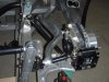
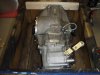
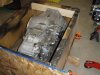
There's absolutely nothing wrong with the G50. The only reason I'm making the change is because a Ricardo has become available at a reasonable price and most of Fran's efforts on the SLC are focussed on the Ricardo at the moment.

How close are you to finishing up that RCR GT40? Considering we're both in MN we need to exchange car visits one of these days! What kind of beer do you like?

Dave L
 

Dave Lindemann

Lifetime Supporter
Dave,

If you don't have a 3" disc lying around you could always draw two "cord" lines through the circle, take 1/2 of each cord width and draw a line perpendicular to the cord toward the center of the circle from those points. They will intersect in the center. :idea:

Doc - I considered that! Too much geometry. I prefer - OK, this disc is the same diameter as the outside of the vent mount on the dash and it has a hole in the middle - much easier!!
 

Dave Lindemann

Lifetime Supporter
A little more progress today. I drilled all of the openings in the front clip. Both headlights are 3.5" diameter and the turn indicators are 2" diameter. I used hole saws and a 1/2" drill again. It worked well though there was some chipping of the gelcoat on the outer edge of the outer headlight opening due to the lack of free space around the outer edge of the hole saw. Hopefully, that makes sense. If I had to do it over again I'd use a smaller hole saw and then enlarge the opening with a drum sander. Fran had sent me some surface mount turn indicators but I decided to go with LED units that have a mounting flange. I'll be installing them from the backside of the clip. I purchased them from superbrightleds.com - MSM Series Marker Lamp w/Flange-Amber MSM-AHP4 for $5.95 each.

I also installed the revised rear upper A-arms that Fran sent me. I still need to install the new billet rocker arms - I ran out of time.

Regards,
Dave L
 

Attachments

  • P2270002.jpg
    P2270002.jpg
    24.1 KB · Views: 466
  • P2270003.jpg
    P2270003.jpg
    33.6 KB · Views: 463
  • P2270004.jpg
    P2270004.jpg
    31.3 KB · Views: 422
  • P2270005.jpg
    P2270005.jpg
    16 KB · Views: 455
  • P2270008.jpg
    P2270008.jpg
    42.3 KB · Views: 477

Dave Lindemann

Lifetime Supporter
Worked on a few small projects today - reversed the way I had the rear upper a-arms installed per a suggestion from Rob Mesa (thanks Rob), started to assemble the billet rocker arms (They had to be pryed apart the tolerances are so close and I need to chill the bearings and warm the billet so the bearings will slide in easily), drilled the hole for the fuel filler (3.5"), removed all of the body to chassis fasteners in preparation for removing the body (need to get some friends to help with the lift), removed the rear bulkhead and fuel tank, and started opening the side vents.

I'd appreciate some input on the side vents before I go much further. Here is what I'm contemplating doing - use a drum sander to bring the openings flush with the top, inner and bottom side walls of the opening but leaving about 1/4" of the outer edge. Then on the backside of the opening I'll 'glass on a fiberglass outer flange so that I can fasten the vent grill material to the flange. This way I can replace the vent grill material if it gets damaged. Thoughts?

Regards,
Dave L
 

Attachments

  • Rear Suspension Revised Upper A-Arm Installed.jpg
    Rear Suspension Revised Upper A-Arm Installed.jpg
    43.5 KB · Views: 577
  • Fuel Filler Hole Drilled.jpg
    Fuel Filler Hole Drilled.jpg
    43.7 KB · Views: 489
  • Fuel Filler Neck in Place.jpg
    Fuel Filler Neck in Place.jpg
    37.4 KB · Views: 497
  • Rocker Arm Prying Apart Halves.jpg
    Rocker Arm Prying Apart Halves.jpg
    33.5 KB · Views: 501
  • Side Vent Preliminary Holes Drilled Close-up.jpg
    Side Vent Preliminary Holes Drilled Close-up.jpg
    34.6 KB · Views: 488
Last edited:
Dave, good point i just glassed mine in and that Al material isn't real stout. I figured if it ripped i'd just grind it all out and start over, but the clamp is a good idea.
 
Dave, your plan for the side vent grille flange is exactly what I'm doing. Made my inner flange 3/8". Using an expanded aluminum mesh (black) for the grilles.
 

Dave Lindemann

Lifetime Supporter
Thanks for the input guys. I hope to be able to do some of the flange work next weekend but we'll see - it's also my wife's B'day!

Dave L
 

Dave Lindemann

Lifetime Supporter
Unfortunately, not much has been happening since my last post due to some family commitments. I picked up the Ricardo from the UPS freight terminal today - beautiful gearbox and boy is it a MONSTER! The starter has been shipped and I just need to decide on which clutch to go with - I'm thinking Stillen. More to come.....

Dave L
 

Howard Jones

Supporter
Dave, I notice that your chassis has a waterpump clearance hole in it. Did that come with? I did sugest to Fran that he do them all like that from now on so as make the car more adaptive to different engines.

How about a close-up of that area. I need to do mine next and it's always good to see what someone else has done with the same issue.
 

Dave Lindemann

Lifetime Supporter
Dave, I notice that your chassis has a waterpump clearance hole in it. Did that come with? I did sugest to Fran that he do them all like that from now on so as make the car more adaptive to different engines.

How about a close-up of that area. I need to do mine next and it's always good to see what someone else has done with the same issue.

Howard - Yes, the chassis came that way. The rear and bottom of the extrusion have been cut out and an aluminum closing plate welded in. Hopefully, the photos will show it better than I can describe it. I threw in a couple shots of the Ricardo too - haven't had time to take it out of the crate.

Regards,
Dave
 

Attachments

  • P4210009.jpg
    P4210009.jpg
    28 KB · Views: 459
  • P4210010.jpg
    P4210010.jpg
    29.5 KB · Views: 441
  • P4210006.jpg
    P4210006.jpg
    39.7 KB · Views: 548
  • P4210007.jpg
    P4210007.jpg
    49.2 KB · Views: 513
out of interest, what does the bare chassis weigh?
I saw you mention that some parts of the chassis are solid aluminium. I didn't know about that.

Regards Thomas
 

Dave Lindemann

Lifetime Supporter
out of interest, what does the bare chassis weigh?
I saw you mention that some parts of the chassis are solid aluminium. I didn't know about that.

Regards Thomas

Sorry Thomas but I haven't stripped the car down that far yet. I would guess that the bare chassis weighs in at a couple hundred pounds but that is just a guess based on when I lifted one with Fran at his shop. The only solid aluminum chassis components are the uprights at the rear of the chassis. Everything else is extruded aluminum.

Regards,
Dave L
 
reversed the way I had the rear upper a-arms installed per a suggestion from Rob Mesa (thanks Rob)
Since the outer rod bearing is not centered along the length of the arm, won't flipping it will move the top of the upright forward (or rearward), hence changing the wheels position in the wheel well and decreasing (or increasing) the wheelbase?

Are you two doing this to avoid contact between the UCA and pushrod when in full droop?
 

Dave Lindemann

Lifetime Supporter
Since the outer rod bearing is not centered along the length of the arm, won't flipping it will move the top of the upright forward (or rearward), hence changing the wheels position in the wheel well and decreasing (or increasing) the wheelbase?

Are you two doing this to avoid contact between the UCA and pushrod when in full droop?

Hi Dave - Yes, flipping the arm will move the top of the upright slightly. By my crude measurements the difference is 1". This is at the upper arm. So, the actual amount the wheel will move is probably less than 1/2". You are correct, this was done to eliminate a small amount of contact I noticed between the upper arm and the pushrod.

Regards,
Dave L
 

Dave Lindemann

Lifetime Supporter
Hi Dave - Yes, flipping the arm will move the top of the upright slightly. By my crude measurements the difference is 1". This is at the upper arm. So, the actual amount the wheel will move is probably less than 1/2". You are correct, this was done to eliminate a small amount of contact I noticed between the upper arm and the pushrod.

Regards,
Dave L

Okay, I've discussed this with Fran and I made a mistake (no big surprise there!). The rear upper a-arm should be installed with the sharp curved profile to the rear (the way I have it now). This orientation eliminates any interference. Sorry for any confusion I may have caused. Here is a photo of the correct orientation.......
 

Attachments

  • rear_upper_control.jpg
    rear_upper_control.jpg
    29.3 KB · Views: 491

Dave Lindemann

Lifetime Supporter
Unfortunately, no progress on the SLC but today I did receive the new "street" rear clip with hinge assembly and openings trimmed. I think it looks great and can't wait to test fit it on the car - the hinge assembly looks fantastic!

Dave L
 

Attachments

  • Street Clip in Truck 2.jpg
    Street Clip in Truck 2.jpg
    44.7 KB · Views: 436
  • Street Clip Unwrapped.jpg
    Street Clip Unwrapped.jpg
    41.4 KB · Views: 469
  • Street Clip Hinge.jpg
    Street Clip Hinge.jpg
    48.3 KB · Views: 417
Back
Top