SLC 007 Dave Lindemann

Dave Lindemann

Lifetime Supporter
Randy - No molds for the Europa, I'll leave all of that work up to Carriage House ;-)

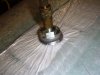
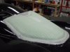
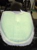
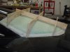
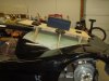
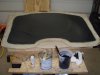
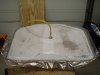
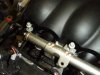
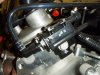
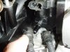
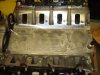
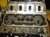
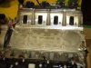
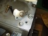
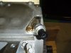
Last weekend I added the foam core and more fiberglass to the mold. Next is to add some structural support then pull it from the body. At the beginning of this process I purchased a new vacuum pump and I've learned a valuable lesson - you can never have too much breather ply under the vacuum fitting! The pump drew resin up through the mat, multiple layers of breather ply and into the end of the vacuum fitting. Next project I'll use a barrier ply. Anyway, here's a few pictures from last weekend.

Dave L
 

Attachments

  • 1-26-13_Foam_Core_Vacuum_Bag.JPG
    1-26-13_Foam_Core_Vacuum_Bag.JPG
    92.4 KB · Views: 334
  • SLC_Rear_Window_Mold_with_Foam_Core_2.JPG
    SLC_Rear_Window_Mold_with_Foam_Core_2.JPG
    73.9 KB · Views: 328
  • SLC_Rear_Window_Mold_with_Foam_Core_3.JPG
    SLC_Rear_Window_Mold_with_Foam_Core_3.JPG
    87.7 KB · Views: 325

Dave Lindemann

Lifetime Supporter
A bit more progress this weekend. I added an interlocking plywood support structure which at this point is just bonded to the mold with construction adhesive. Fiberglass reinforcement will be added where the plywood attaches to the mold then I can finally remove the mold from the car. I plan to mold my first part next weekend - wish me luck!

Dave L
 

Attachments

  • Plywood Support for Mold 2.JPG
    Plywood Support for Mold 2.JPG
    156.8 KB · Views: 297
  • Plywood Support for Mold 1.JPG
    Plywood Support for Mold 1.JPG
    158 KB · Views: 309
Very impressive work Dave!! You actually look like you know what your doing!! :thumbsup: This will be a work of art when your done.
 

Dave Lindemann

Lifetime Supporter
Thanks Doc - somehow I missed your post until now? - Sorry about that. The jury is still out regarding whether I know what I'm doing - but I'm having fun!

With all the care I took to try and get a good mold surface I still had to fill, sand, fill, sand some more, fill, sand, buff - well, you get the idea. All of the imperfections were small but I could see/feel them. A fiberglass part has finally been made - but it's still in the mold curing. I want to leave it for a week to fully cure. I applied surfacing primer first, 2 layers of fine mat, 1 layer of heavy mat, 2 layers of woven fabric finished off with another layer of mat - all vacuum bagged. It should be a very strong yet light weight part when finished. Next up is carbon fiber......

Dave L
 

Attachments

  • Mold_With_Surfacing_Primer_Applied.JPG
    Mold_With_Surfacing_Primer_Applied.JPG
    159.9 KB · Views: 290
  • SLC_Rear_Window_Part_Under_Vacuum.JPG
    SLC_Rear_Window_Part_Under_Vacuum.JPG
    150.7 KB · Views: 294

Dave Lindemann

Lifetime Supporter
OK, so I've decided to sell the SLC. To possibly help the sale I've decided to complete some tasks that some folks may not want to deal with. First is reversing the intake. This is not a difficult task and the Corvette service manuals make it really easy.

1. Loosen/remove the 10 intake mounting bolts using an 8mm socket.
2. Remove the EVAP valve/bracket from the right front of the head using a 15mm socket.
3. Disconnect PCV hose.
4. Lift off the intake.
5. Remove the oil pressure sensor from the valley cover.
6. Remove the 10 bolts securing the valley cover using a 13mm socket.
7. Remove the valley cover and gasket.
8. Install the new valley cover gasket and the O-ring in the oil sensor mount and then the valley cover (all from Katech). Hand tighten the new bolts including the Katech supplied specialty fasteners (one is a 5mm allen drive) for the modified oil sensor mount. Torque all fasteners to 18 lb ft.
9. Install the intake in the reversed position.
10. Apply threadlocker (GM Part #12345382 - or Loctite 242 - medium strength, Blue) to the intake mounting bolts and tighten to 44 lb in on the first pass (criss-cross tightening pattern beginning in the center), then 89 lb in on the second pass.
11. Mount the EVAP valve/bracket on the left head at the rear and tighten to 37 lb ft.

I think that's pretty much it - if I missed something please let me know.

Next, I will be installing the flywheel , clutch, and mating the Ricardo with the LS3 and installing them in the chassis. If nothing else this will make shipping easier - not to mention a few less steps in the build process for the next owner/builder.

Regards,
Dave L
 

Attachments

  • 1 - LS3 Stock Intake Orientation.JPG
    1 - LS3 Stock Intake Orientation.JPG
    145.2 KB · Views: 293
  • 2 - LS3 Intake Bolt Removal.JPG
    2 - LS3 Intake Bolt Removal.JPG
    151.6 KB · Views: 278
  • 3 - LS3 EVAP Valve and  Bracket on Front of Head.JPG
    3 - LS3 EVAP Valve and Bracket on Front of Head.JPG
    157.5 KB · Views: 435
  • 4 - LS3 PCV Hose Removed.JPG
    4 - LS3 PCV Hose Removed.JPG
    145 KB · Views: 590
  • 5 - LS3 Intake Removed - Stock Valley Cover.JPG
    5 - LS3 Intake Removed - Stock Valley Cover.JPG
    153 KB · Views: 333
  • 6 - LS3 Stock Valley Cover Removed - Gasket Still in Place.JPG
    6 - LS3 Stock Valley Cover Removed - Gasket Still in Place.JPG
    149.1 KB · Views: 1,035
  • 7 - LS3 Katech Valley Cover Installed.JPG
    7 - LS3 Katech Valley Cover Installed.JPG
    144.3 KB · Views: 680
  • 8 - LS3 Katech Oil P Sender Mount with O-Ring and Mounting Hdwre.JPG
    8 - LS3 Katech Oil P Sender Mount with O-Ring and Mounting Hdwre.JPG
    138.5 KB · Views: 359
  • 9 - LS3 Katech Oil P Mount with Sender.JPG
    9 - LS3 Katech Oil P Mount with Sender.JPG
    147.7 KB · Views: 359
  • 10 - LS3 Intake Reversed.JPG
    10 - LS3 Intake Reversed.JPG
    146.2 KB · Views: 348
  • 11 - LS3 Katech Oil P Sender Adapter Clearance.JPG
    11 - LS3 Katech Oil P Sender Adapter Clearance.JPG
    149.6 KB · Views: 297
Back
Top