Suspension setup

Malcolm,

If you can provide me with the x,y & z coordinates of your inboard and outboard pickup points (trailing and transverse), I'll see what I can do for minimizing your roll steer.
If you use a tape measure and plumbob on a flat floor at your wanted static ride height, you should be able to get accuracies of +/- 1mm. It might be worth trying this before you go to the expense and bother of parallel lower transverse links.

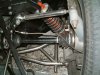
One of the problems in analysing the GTD rear suspension is that the lower radius arm is vertically offset from the lower transverse arm on the rear upright and this means that the trailing arm pickup point moves through a complex curve as the suspension moves up and down.
The curve is influenced by both the upper and lower transverse arms. The location of the front of the trailing arm is critical to matching this curve, adjusting castor doesn't seem to be as effective.

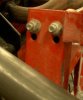
The adjustments would mean you have to build a couple of offset u-brackets plus shims. If you want to try this, it would be useful if you could measure the roll steer before and after the adjustments, to ensure we are on the same page.
 
It would make a fascinating read if you both Trevor & Malcolm could do the measurments & calculations on this forum. My self & I'm sure lots of others would be very interested.

I don't know if al GTD's were made this way, but mine has a choice of chassis pickup points for the rear trailing (radius?) arms.

I assume there is some anti-dive engineered into the chassis, in that the chassis member that picks up the trailing arms is canted rearward, but I don't know why a choice of locations is offered...
 
Hi Malcolm,
I wasn't happy with the rear of my GTD so along with Brian Magee we fabricated new radius rods, lower wishbones and top links to replicate as near as possible (subject to GTD chassis design constraints)the setup on the original Monocoques, canted the uprights back 7.5 degrees, and moved the top link inboard position up with full adjustment at all the joints, I think it is possible to get a good setup without going to parallel lower arms
 

Attachments

  • 21954-DSCF11a.JPG
    21954-DSCF11a.JPG
    24.9 KB · Views: 463
Hello All, I will chip in here if thats ok. The rear of the GTD is not the only problem, the front is no better either. Many of the race lads, Malcolm, Roy, and others have done things here too.

The Rear hub carriers on the GTD were never really fully developed. The top mount fixing was incorrect, the pivot points were also nothing more than rudementary. Due to the fact that most GTD went out on Rubber bushes and adjustment was down to shimming the bracketry. Where do you start. Most have gone the Rose joint or adjustable suspension as a fix. Some have gone ally uprights and improved the pivot points. I like Bob Putnams design for parallel pivot, though it would mean heavy mods for most GTD guys. Though if they were to lower their engines at the same time by bringing the gearbox lower at the rear, then they could weld new brackets in the correct positions at the same time! Just a suggestion.

There are ways to improve the old set up but it does involve an adjustable top link and a modified bracket. It all depends on whether the owner intends to use the old steel carriers or switch to ally uprights. With ally uprights, you have the ability to manipulate the brackets and the way it is mounted. The old style steel version is kind of set in its format (And very heavy 23 kilos all up!!)

One of the guys at GTD realized by drilling a new mounting hole for the top link on the steel carrier, it helped the situation a little, but to make it work properly the steel carriers are in the bin..

Derek Bell (GTD Lola T70 Mk3B) has also done a whole load of sums and calculations regarding suspension and the GTD handling characteristics. His findings has improve his Lolas Handling totally.

It would take hours and hours to list all the possible connetations of suspension tuning here, and it really is down to customer choices and tyre types etc etc.

best regards

Mark Sibley
MDA
 

Brian Kissel

Staff member
Admin
Lifetime Supporter
A link to Derek Bells information on GTD suspension setup, and revamping, can be found here GTD suspension .
It is very good reading.
/ubbthreads/images/graemlins/smile.gif
Brian
 
Lola, I'll second that. Derek's articles make good reading.

Interestingly he makes comment on the rear GTD suspension having too much camber change in it's movement & he addresses the problem by relocating the top arm pickup point.

Another way to reduce camber change would be to shorten the bottom A-arm. This has a side effect of reducing the track during the movement of the suspension....

HOWEVER, making mods to the GTD chassis, (is it Andrew Fordyce?) to spread the lower longitudinal members that pickup the A-arms and hence shortening the A-arms will allow the transaxle to be lowered significantly.

Interesting eh?! /ubbthreads/images/graemlins/wink.gif
 
What great articles! I wish I had seen them before. Looks like we took really similar approaches to the problems.

The 3rd fig in the 1st article on suspensions is a really good illustration of the 'sweet spot' I was talking about earlier.
There is one small observation I would make about that 3rd figure. I order to compare apples to apples the static toe for the lower position measurement should have been reset to 0 at nominal ride height (by shimming the radius arm).

This would mean that the whole curve for the lower position should be shifted up so that it passes through the origin (suspension travel = 0).
If you do that you can see that you reduce roll steer to less than 1/3 of that from the upper position curve over the critical region from static to 2" compression.

His analysis of camber compensation is spot on. I came to very similar conclusions; ie that the upper inboard link must be raised. Have included a photo of the offset bracket I fabricated to raise this pickup point and reduce camber compensation. Used 5mm thick stainless to ensure strength was sufficient.
 

Attachments

  • 21980-offset bracket.JPG
    21980-offset bracket.JPG
    56.9 KB · Views: 428

Malcolm

Supporter
Very interesting posts above. I only lobbed out the idea of parallel lower link arms as a discussion topic and I hit pay dirt levels of interest. Good. I wasn't planning on making any changes to my car. Also at present I am not in a position to take measurements from my car as no garage. New garage soon to be constructed, with specific attention given to level floor for suspension set ups.

Some of the comments above seem to take the "bad" GTD suspension issues a bit far. I do not disagree with comments about the theoretical suspension attributes of a GTD but I like the practical attributes of the car very much. It handles very well. YOU JUST NEED TO SET IT UP PROPERLY. I think this is where most GTD owners come unstuck and perhaps are not aware of it.

From my time with standard GTD suspension I seem to remember being quite quick. Robin and I attended Brands Hatch on the full GP circuit (the best in the world?) and got well in excess of 50 laps in. We were up against all modern road going porsche, TVR and Ferrari. Only the Ferrari 288 GTO Evolution and F40 were quicker than us, as they should be.

Look at this another way. The Goodwood Rivival GT40s have professional drivers. If I said the origianl GT40s handled badly then I would be taken out and shot! So with that bench mark, in a really standard GTD I was able to be timed at 1 min 38 secs on Comp TA road tyres with completely standard suspension, the old solid disc rear brake set up with Granada front brakes, all way back in 1994. This says to me that the car is fundamentally a good car for handling. The top Revival 40s are about 10 secs lap quciker. We shall what happens this coming weekend.

And didn't an uprated GTD win the Swedish GT championship for two years running when up against the latest race Porshces etc?

Lowering your engine has to help handling and one day I will do this. If you are building now, do it, it pays great dividends!

Am I on a hobby horse here? Ooops, stop now.... Sorry!

Malcolm /ubbthreads/images/graemlins/wink.gif
 

Malcolm

Supporter
Just reread your post, Julian. Do not change your chassis trailing arm pick up position to the other chassis option. If you use the other holes your handling will disappear and the back end of your car will become the front end very quickly. Weld the holes up to remove the temptation! No one I know of has done this and been pleased with the results. Some got body damage along the way!

Malcolm
 

Malcolm

Supporter
I am going to have to look at my car as I can't remember off the top of my head. Will try and reply tomorrow.

Malcolm
 
Howard, Malcolm,

IMO the choice of mounting holes depends on ride height and diameter of rear tyres. If you are running low ground clearance ( less than 4.5") then I would suggest the upper hole, but if you are going to run about 5" or above then the lower hole will give you less bump/roll steer.

I would guess that might be the original idea for providing the 2 positions, but that's just a guess. You can still use the upper hole with high ride height but you will have to introduce static toe-in at the rear to avoid toe out at suspension compression.

The above comments are based on using standard GTD suspension brackets.
 
Guys,

Just wanted to thank everyone who participated in this thread. It has really helped me improve my understanding of the GT40 rear suspension.

When I started out building the car many years ago, my main concerns were camber compensation and location of front and rear roll centres. The original GT40 had 4.1" and 4.6" roll centres respectively with a ground clearance of 4.8". I designed the front suspension with that in mind. The rear suspension was based on the GTD and I fiddled with link angles until I was happy.
Although I measured rear toe-in and roll steer initially, I didn't appreciate how sensitive the handling was to roll steer until I drove it.

From posts in this thread, it made me realise that the only way to introduce anti-squat geometry into the rear and still maintain minimum roll-steer and correct roll centre height is to introduce castor. Anti-squat is certainly useful in exiting corners when the outside suspension is under compression and an application of power will further compress the suspension unless the suspension incorporates anti-squat. Greater compression of the rear suspension has two potentially bad effects, it can increase roll steer and driveshafts can reach more extreme angles under full power making them more likely to break (especially with a limited slip diff).

The usual way of creating anti-squat geometry is to raise the front of the lower radius arm so it is pointing closer to the C of G of the car. Tilting the top of the upright backwards allows you to do this while still controlling the roll centre and minimizing roll steer.

The analysis becomes more complex because the rear upright is now rotating both in castor (due to non-parallel radius arms) and camber simultaneously as the suspension moves up and down. I now realize my relatively simple computer model was not accurate enough to account for larger castor rotation with suspension travel and am upgrading it. I should probably use a commercial CAD program, but; a) you learn more by doing it yourself and; b) it's a chunk of money better spent elsewhere.

One of the aims I had before building the car was to gain a better understanding of suspensions. Thanks to help from people on this forum, I am slowly getting there.

Ron and Hershal, thanks for creating/maintaining this forum where enthusiasts for all over the world can come together to discuss their favourite passion.
 
With reference to the choice of mounting holes for the radius arms, my car has the pickups in the top position. The suspension was apparentley assembled and fitted at GTD.

FWIW my car was very unstable in a straight line & would wander all over the place, however it would behave OK when cornering, ie with the suspension loaded up.

The straight line instability could have been caused by any number of mal-adjustments, but Trevors explanation would indicate the pickups were wrong, especially with the standard ride height of 6"....

Also I'd like to second Trevors comments re this great forum & the wealth of technical knowledge available to enthusiasts. /ubbthreads/images/graemlins/cool.gif
 

Attachments

  • 22365-14-9-03 007.jpg
    22365-14-9-03 007.jpg
    37.4 KB · Views: 398

Malcolm

Supporter
Have had a look at my car now, apologies for taking so long. I run using the top holes, the same as Julian West referred to above. However as I don't have a high speed stability issue as he describes maybe, Julian, you have another source for that other than these mounting holes. I think that the lower holes induce rear end instability in corners not the straights. Damper settings, tyre/wheel rim sizes, steering componentry could all lead to instability at high speed, plus most likely a whole lot of other stuff I can't think of.

Malcolm
 
Hi Malc,

It wasn't really "high speed instability", just "straight line instability". At the time I made a few adjustemnts to the castor & ride height which helped a little.

However, now the car is undergoing such a major re-work I'm hoping for a big improvement. /ubbthreads/images/graemlins/cool.gif
 
Julian,

Here's a procedure I've worked out that allows you to achieve both minimum roll steer and anti-squat; ie the upper hole of the trailing arm:

1) at your wanted ride height, measure the vertical distance of the front and rear lower trailing arm. If the front is 3 cm higher than the rear, for example,this means that it is sloping up at about 2.5 deg (arcsin (3/69.5)) where 69.5 is length of trailing arm.
2) since you will now be using rose jointed suspension, align rear toe-in to the desired static value (probably between 0 and 0.2 degs)
3) now adjust (increase) the length of the upper trailing link so that you have nearly the same amount of castor as trailing arm slope; if as in my example, about 2.5 degs. Castor is increased by adding shims between the upper trailing arm pickup bracket and the upright.
Castor angle can be determined by measuring the vertical heights of the lower front and rear transverse pickup points on the upright.
In my case the front of the upright should be about 9 mm (note correction from before) higher than the rear. In reality the lower inboard brackets should be modified (angled), but for small angles, they may be all right as is.
4) It is now criticial to re-measure your static toe and also measure the roll-steer by either using a guage or building you own set-up like Alan Staniforth's or Fred Puhn's books suggest.
5) If you find that the suspension is still toeing out or toe in is reducing with suspension compression, increase castor until it doesn't.

Although this is a bit of a fiddly proceedure, when you are finished, you should have both minimum roll-steer and some anti-squat, which can't be bad.

Good luck
 
Great, Thanks Trevor.

I'll use your technique & let you know how I get on. I'm hoping to progress to my chassis mods in a week or so & will soon be getting on with the initial setup.

Best Regards,
 
Back
Top