Toms RCR 40 Trackracer

Status
Not open for further replies.
ACCUSUMP:

I´m going to install a 3 quart EPC controlled ACCUSUMP.

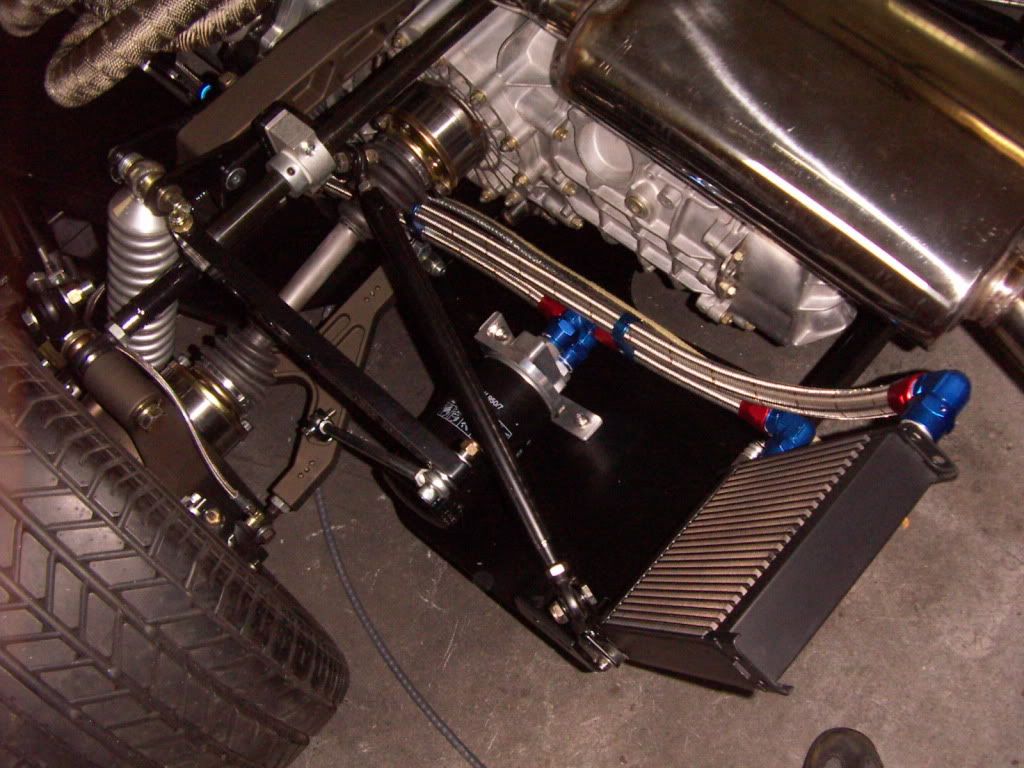
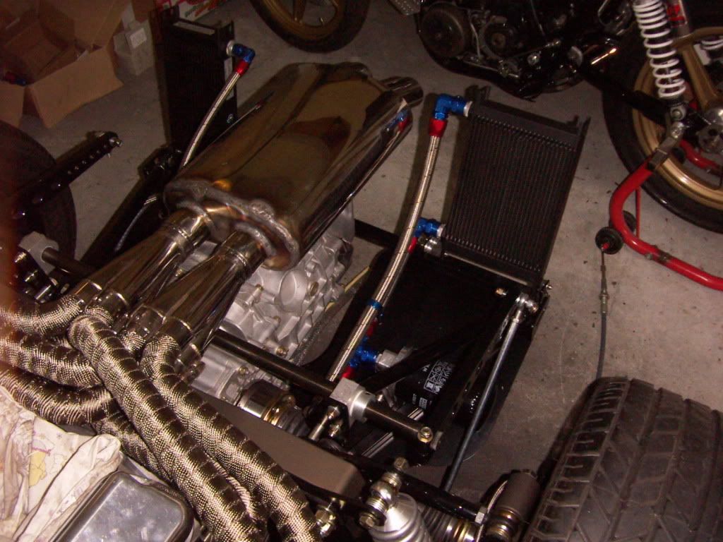
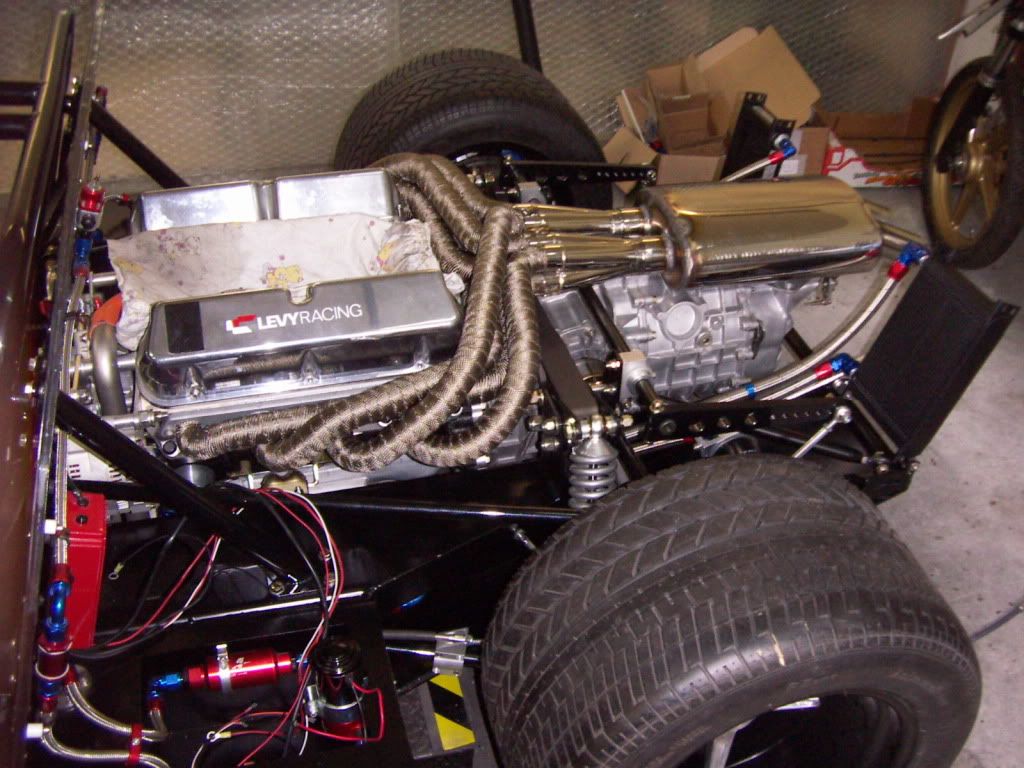
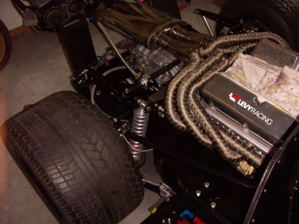
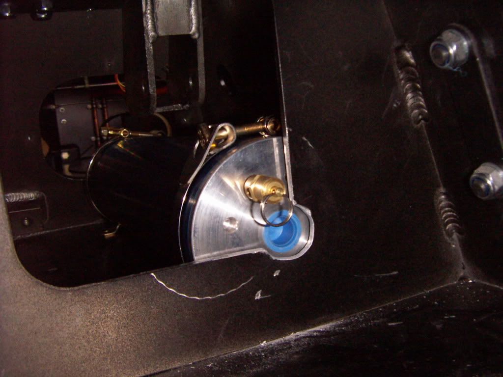
I placed the tank right behind the passenger side firewall in the inner sidepods. It is a very close fit in there but it fits. I think a perfect location. It is not visible there, the side pod can work as catch tank if something leaks, good also in terms of weight distribution. Short lines can be realised. In order to make it fit there, i had to adapt two small things.
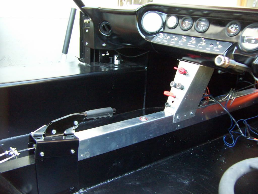
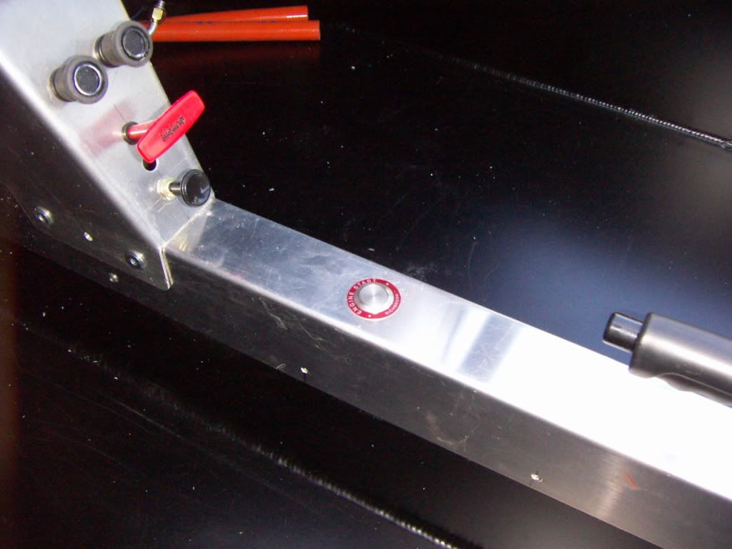
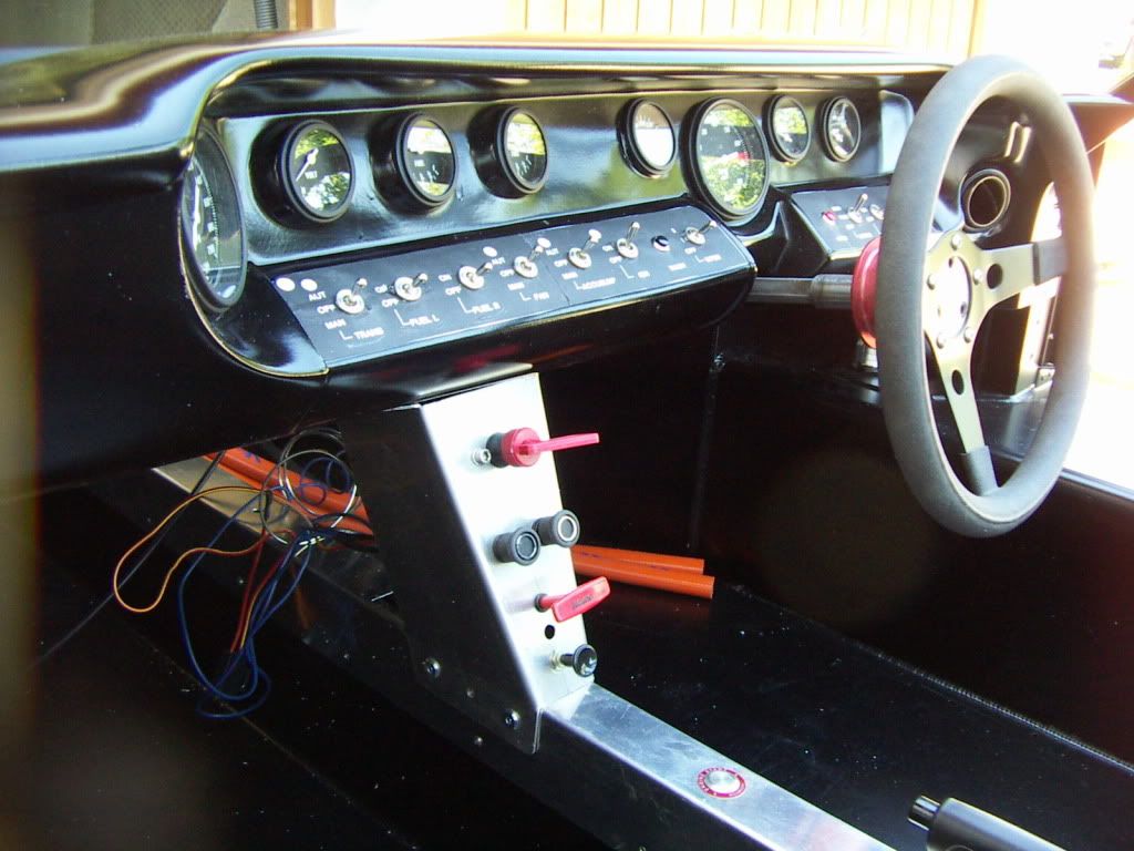
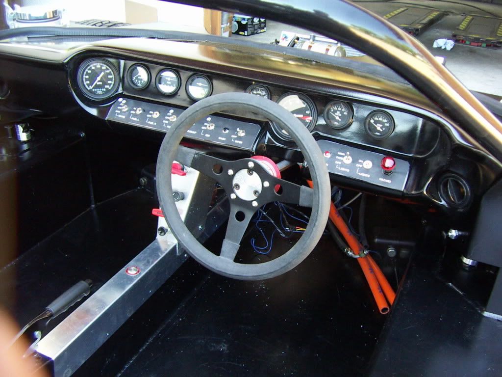
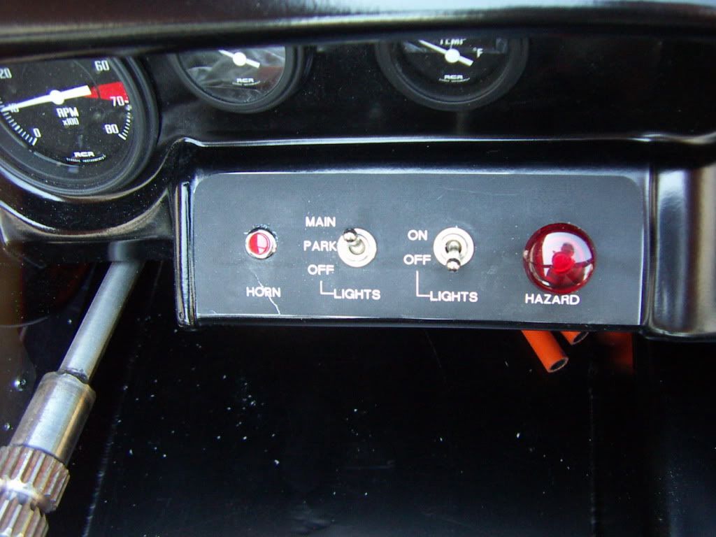
First the original pressure gauge adds to much to the total lenght and has to be relocated. I will place a nice smaller one in my middle tunnel, so that it is visible from the drivers position. This will give me a second oil pressure gauge ( just plus 7 PSI for the air) Hey RUSS what you think ? The other thing to adapt was a small notch out in the side pod for clearing the pressure line fitting.

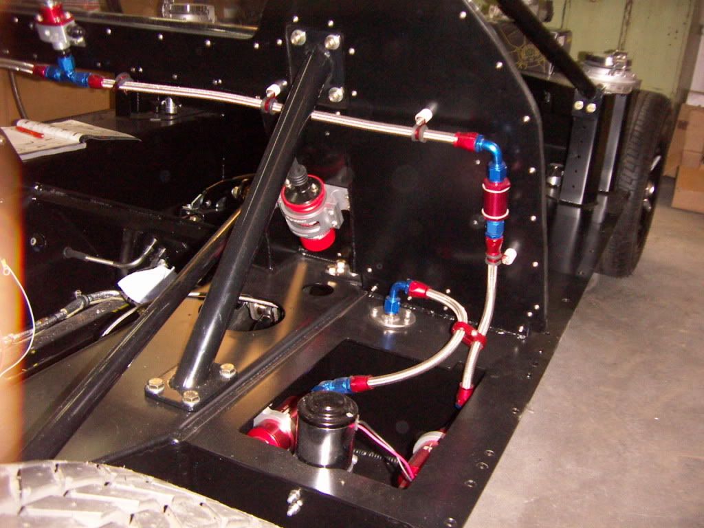
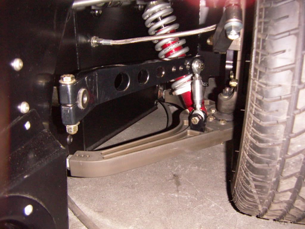
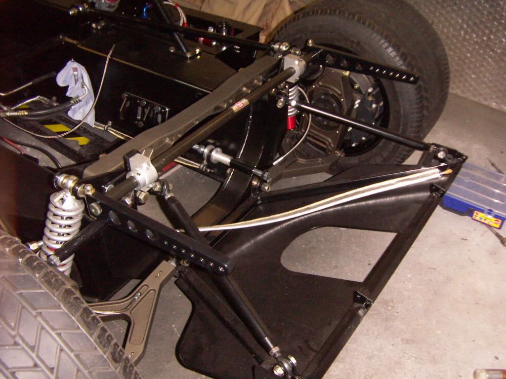
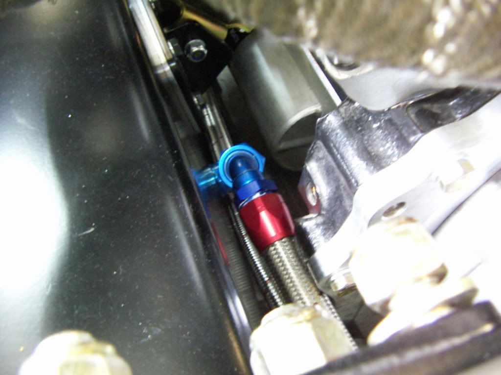
Radius rod in lowest position still clears
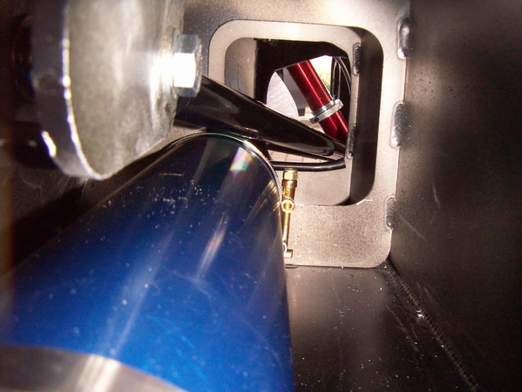
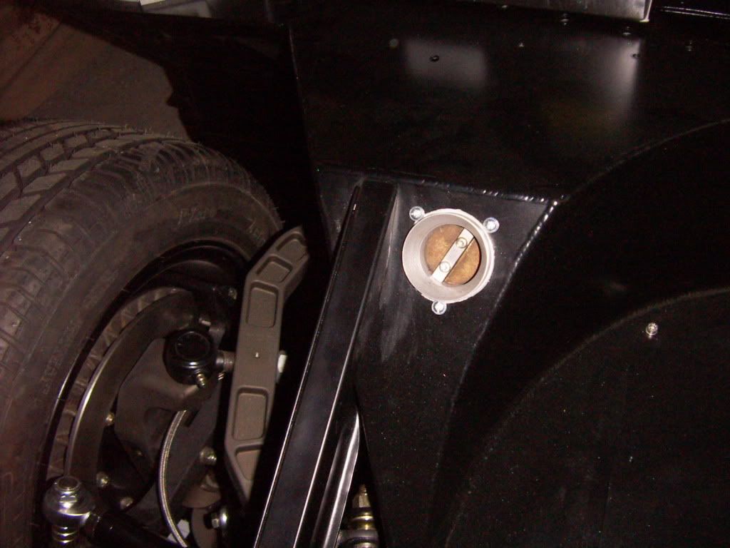
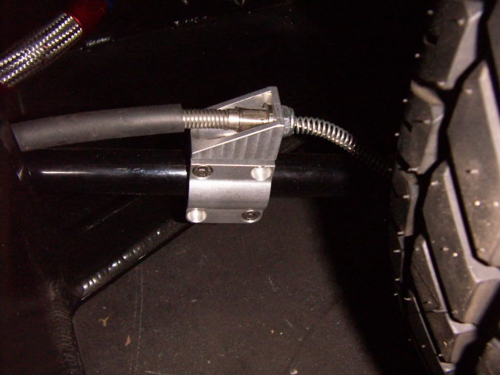
PICT4165.jpg


side pod notch out
PICT4155.jpg


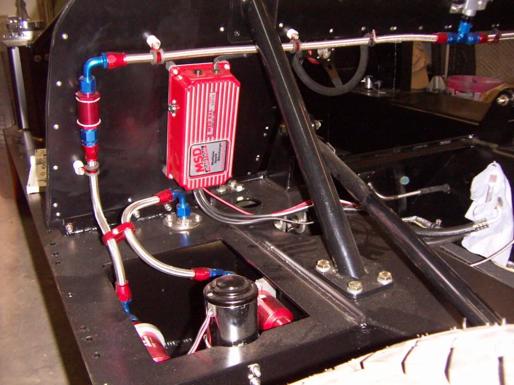
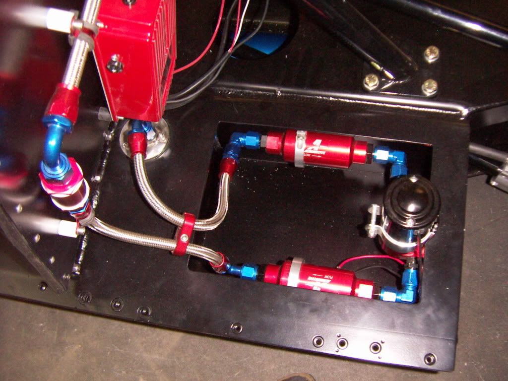
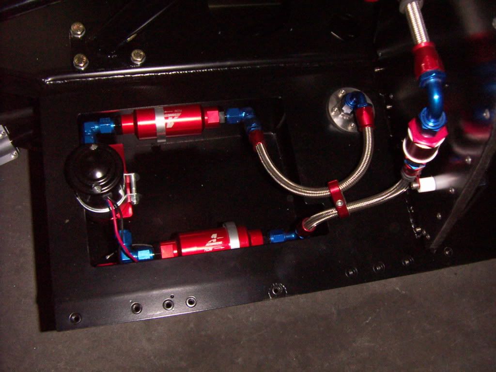
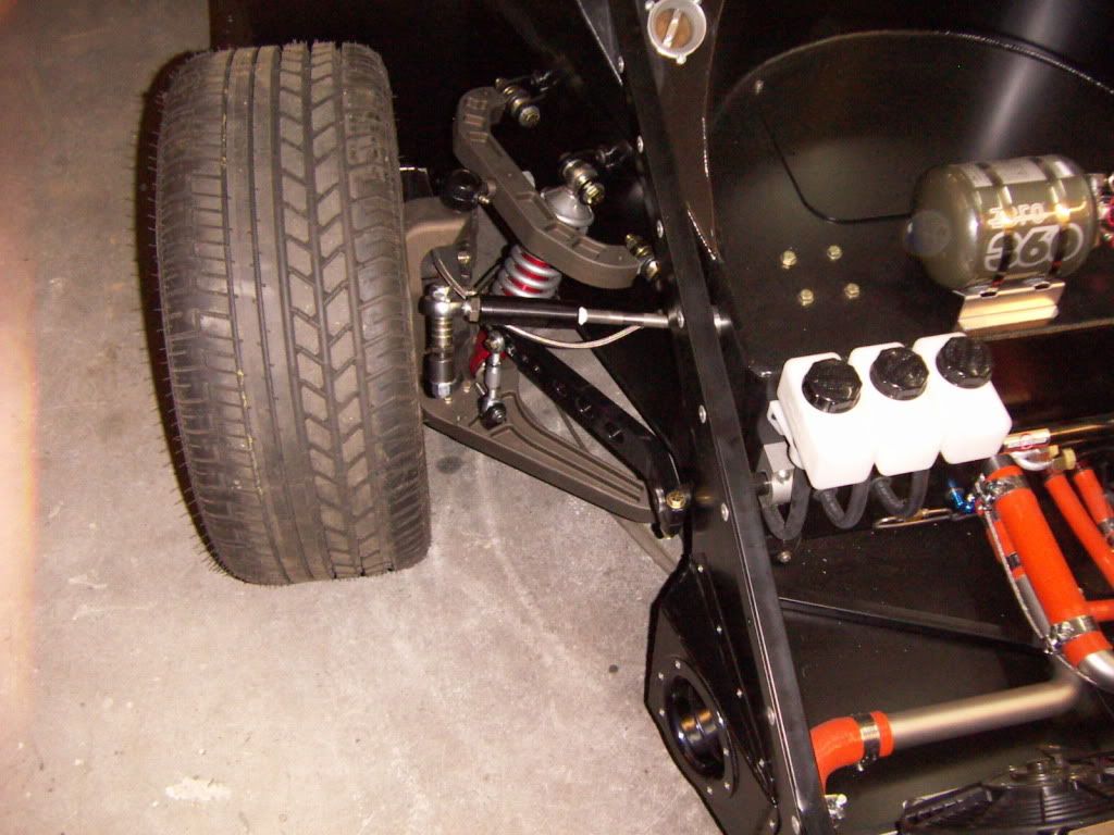
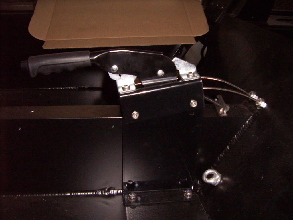
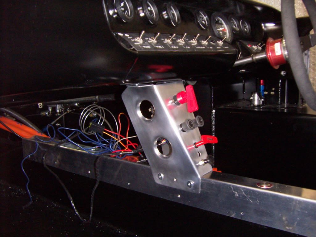
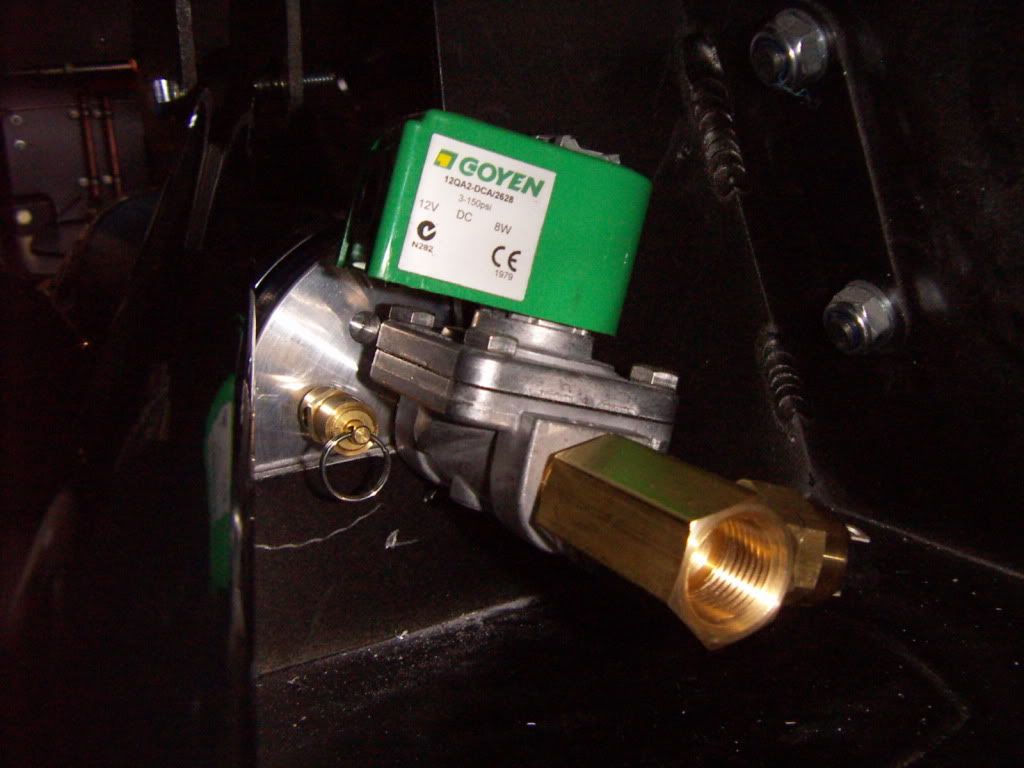
installed with the epc controller and valve
PICT4163.jpg


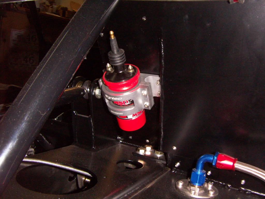
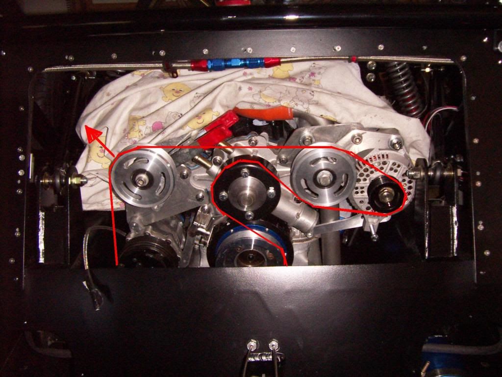
Front change to relocated pressure gauge . I´m using braided teflon hose for the first 15 " because of the heat, the rest is standard teflon hose. Love that nice little gauge.
PICT4160.jpg


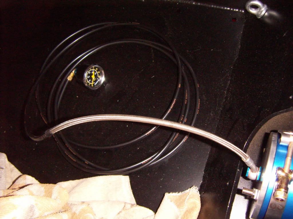
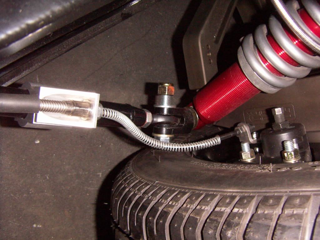
Connection to the pressure line will be done with AN12 lines and an AN12 bulkead T. throught the sidewall of the engine sidepod.

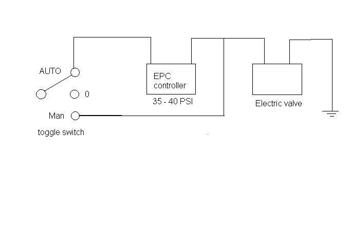
The electric installation will be done in a way that the valve is either pressure controlled activated or manually activated
ACCUSUMP.jpg


TOM

AWH: 721 h
 
Last edited:
Hi Tom,

I have to say what you did with the RCR FRONT is awesome. So what will it cost me to get this upgrade from you to put on my RCR?

Hint....Hint.....
 
A little update,

installed a few more items

FUelsystem: installed the filters and pump on elastic elements. checked the pumps and also the fueltanksensors. everything works ok ( at least dry).
PICT4167.jpg


PICT4168.jpg


PICT4169.jpg


PICT4171.jpg


Ignition: Mounted the MSD box and the ignition coil. I have decided to mount the coil away from the box in order to have a nicer wire routing and less interference. Found a nice cnc bracket for the coil, which is originaly intended to be used for a fuel pump.
PICT4170.jpg

Freshair supply: Adapted a Ford Focus throttle body for creation of a fresh air inlet regulation. Due to the channels made in the front clip the NACA ducts directly supply fresh air to this throttle body. There will be a pull/push cable for each side, so the passenger and driver can choose there adjustments separately.
PICT4175.jpg

Swaybars: Finished installation of the front sway bar. The arms where powdercoated highgloss black. During the installation i checked for binding of the droplinks, in order to find a position of the lower mounting bracket, where a full suspension movement can be done without any binding.
Also installed the rear swaybar. Just need to fabricate the droplinks.
PICT4174.jpg


PICT4177.jpg


PICT4172.jpg


TOM

AWH:735h
 
Last edited:
Been pretty busy on the car

Installed emergency brake system. I have my cousin fabricating brackets for the pull cable which are mounted on the lower radius rod.

PICT4183.jpg


PICT4184.jpg


I mounted the brake lever as much towards the firewall as possible and also inclined it towards the front. This way the lever clears ones elbow nicely in fast steering actions.
PICT4181.jpg


I have the engine back in the car. I also installed the clutch and gearbox.
For my GT2 clutch setup i had to fit the pilot bearing in the correct depth. for this a 8mm high spacer was made. THe SBF crank has the same 35mm hole for the pilot bearing as the porsches, so i used a stock porsche ball race pilot bearing.
PICT4194.jpg


PICT4195.jpg


PICT4196.jpg


PICT4197.jpg


to center the frictionplate i used a curt off G50 input shaft.
PICT4004.jpg


to install the release lever one have to fix it upfront with rubberbands.
PICT4198.jpg


The gearbox went in very smooth, everything fitted perfect. one can reach the pulllever through an accesshole in the gearbox and slip in the lever axle and bearings.

The oilcoolers for engine and gearbox where reinstalled. The pressure line from the accusump was connected via an AN12 bulkhead T.
PICT4200.jpg


PICT4201.jpg


PICT4204.jpg


Also have my serpentine system mocked up. some spacers to make and the belt to measure and order, than this task is also finished.

serpentinesetup.jpg


Reinhard helped me to wrap the headers with DEI Titanium header wrap. This should help to keep the temperatures lower below the rear clip and it looks great. It was much better to apply than i have feared. THis wrap is not as stiff as others i know, no need to wet it for application.

PICT4199.jpg


PICT4207.jpg


TOM

AWH: 760h
 
The front trim on my engine is very similar to yours. I would recommend replacing one of your idlers with a spring tensioner. I cannot get my belt to stop squealing when the engine is cold and the AC is on.
 
The front trim on my engine is very similar to yours. I would recommend replacing one of your idlers with a spring tensioner. I cannot get my belt to stop squealing when the engine is cold and the AC is on.

The one to the upper left corner is a spring tensioner. red arrow shows tensioning direction

Thanks
TOM
 
"so i used a stock porsche ball race pilot bearing"
i don't know how much you payed for your "race pilot bearing" at the Porsche dealer, but this is a standard 6302 ball bearing with two rubber sealing rings, usually runs about 2 to 4 dollars per piece.
 

Randy V

Moderator-Admin
Staff member
Admin
Lifetime Supporter
Very nice work Tom. I see I have missed seeing a number of your updates. I will be taking similar course with my trans and engine oil coolant lines. Bill M also did this with fans which are in my plans as well.
The treatment of the suspension parts in the magnesium look is superb!!!
The front/rear sway bars I also like. I'm hoping to find the same. What diameters would they be?

Thanks for sharing your build with us!
 
i don't know how much you payed for your "race pilot bearing" at the Porsche dealer, but this is a standard 6302 ball bearing with two rubber sealing rings, usually runs about 2 to 4 dollars per piece.


Exactly that´s what it is. And trust me i did not buy it at the p dealership

TOM

RANDY

both swaybars are 1". Basically i have designed the arm lengths in a way that all corners have a wheel rate in total of app 300 lbs/ inch (front 50/50 spring / swaybar, rear 60/40 Spring / swaybar) in the softest postion of the droplinks to the swaybar arms. Hope this is a good basic setting and will go from there.
FInd attached an excel chart i did for this purpose.


TOM
 

Attachments

  • SUSPENSIONCALCULATIONSfrontmyrcr.xls
    47.5 KB · Views: 361
Did you get any data from Levy racing concerning the exhaust wrapping? How much is your overlap? Did you do single or double? Your heads are going to run a little hotter when using wrap, but in most cases this influence is negligible. Any idea on increase in HP?
 
Did you get any data from Levy racing concerning the exhaust wrapping? How much is your overlap? Did you do single or double? Your heads are going to run a little hotter when using wrap, but in most cases this influence is negligible. Any idea on increase in HP?

HI Brisc ( btw what´s your name?)

Which data´s should i request from Gordon ?

overlap is app 1/3 of the tapewidth ( 2" tape)

Had no intention to increase HP ( plenty anyway). My target is to reduce temps underneath the rearclip, but if it increases HP, fine with me.

Thanks
TOM
 
Worked on my interiour quite a bit yesterday.

installed my center tunnel cover and made a center console out of aluminium. This center console is housing the emergency cut off switch, the AC controls and the pull levers for the fire system and heater valve
It also helps to support the dashboard and makes the whole installation very rigid.

PICT4215.jpg


the starter button is located in the center cover

PICT4216.jpg


Mocked up my switch panels with a printout of the engraphed anodised cover a company will make for me. I did this to check the switch location and the look of it. Like it very much.
PICT4217.jpg


PICT4212.jpg


You can also see the little pull knobs under the eyeball vents. This are the pull cables to open and close the fresh air valves coming from the NACA ducts of the front clip.
PICT4213.jpg


PICT4214.jpg


TOM

Awh: 778h
 
Last edited:
Tom,

Just going back a post or three. About your suspension calculation sheet. It doesn't look like your installation ratio calculations for the springs or roll bars makes sense to me. You are supposed to use the IR squared in order to calculate the wheel spring rate. Unless you are compensating for this factor somewhere else in your equations...not sure.

I do have a comprehensive suspension calculation sheet for my DRB GT40 which should be readily adaptable to your RCR if you like.

Cheers,

Julian
 
HI Brisc ( btw what´s your name?)

Which data´s should i request from Gordon ?

overlap is app 1/3 of the tapewidth ( 2" tape)

Had no intention to increase HP ( plenty anyway). My target is to reduce temps underneath the rearclip, but if it increases HP, fine with me.

Thanks
TOM

that's why most headers these days are double wall, to keep inner tube temperatures up. When the valve opens, there's a shock/sound wave travelling down the exhaust, as soon as it expands (when it comes out of the exhaust) there's a rarefaction wave travelling back "sucking" combustion gases out of the engine. This of course only works at one rpm, hence the divergent end pieces in many exhausts. The shock/sound wave however slows down if it has to heat the walls... ...but I'm sure that this is just the theoretical side - how much more HP it makes is another question to answer
 
Tom,

Just going back a post or three. About your suspension calculation sheet. It doesn't look like your installation ratio calculations for the springs or roll bars makes sense to me. You are supposed to use the IR squared in order to calculate the wheel spring rate. Unless you are compensating for this factor somewhere else in your equations...not sure.

I do have a comprehensive suspension calculation sheet for my DRB GT40 which should be readily adaptable to your RCR if you like.

Cheers,

Julian

Hi Julian,

Please detail a little more your concern.

I made this with my knowledge of physics and have not consulted any smart bock, so i could be wrong.
here just they way i thought it should be:
Wheelrate is the force at the center of the tires contact patch working against the resistance force created by the spring and swaybar.

Springrate efficient at the shock mounting point is a function of the sinus. ( at 90° , vertical shock it would be equal to the spring rate named on the spring).
Wheelrate is than just a plain law of lever calculation. Don´t know where a squared function should come in. Same accounts for wheelrate of swaybar.

But as said, i could be wrong, please correct if so.

THanks
TOM
 

Randy V

Moderator-Admin
Staff member
Admin
Lifetime Supporter
that's why most headers these days are double wall, to keep inner tube temperatures up. When the valve opens, there's a shock/sound wave travelling down the exhaust, as soon as it expands (when it comes out of the exhaust) there's a rarefaction wave travelling back "sucking" combustion gases out of the engine. This of course only works at one rpm, hence the divergent end pieces in many exhausts. The shock/sound wave however slows down if it has to heat the walls... ...but I'm sure that this is just the theoretical side - how much more HP it makes is another question to answer

Not to cause a hi-jack on Tom's thread - so maybe we should take this to another thread.

I know of no automotive header that is double-wall - however a lot of motorcycle exhausts are made this way.
I am not certain as to the validity of your physics in regard to a sound wave slowing down because it needs to heat a surface that is to reflect it...
 
Status
Not open for further replies.
Back
Top