

You are using an out of date browser. It may not display this or other websites correctly.
You should upgrade or use an alternative browser.
You should upgrade or use an alternative browser.
Toms RCR 40 Trackracer
- Thread starter EGLITOM
- Start date
- Status
- Not open for further replies.

Not to cause a hi-jack on Tom's thread - so maybe we should take this to another thread.
I know of no automotive header that is double-wall - however a lot of motorcycle exhausts are made this way.
.
I think the factory LS7 header is double wall. It looks like it when I peer down the port, anyway.
Yeah, we should start our own thread on this. What I've written there was from our gasdynamics lecture, and the prof had as an example a double wall header with him, can't remember what off, bmw, merc or porsche. It only makes a tiny improvement, and it's just at that limit where the additional cost might not make it worth.
the gas behind the sound/shock wave (will be a shock wave with maybe only Mach 1.001) is what matters, the hotter it is, the higher the pressure, since the sound/shock wave won't be influenced much by wall temperature (well the boundary layer is there as well, it can increase or decrease for cold walls, can't remember however what that parameter was). When the sound wave (etc. the contact surface) exits from the exhaust, the pressure difference will define the strength of the rarefaction wave travelling back (rarefaction waves always travel at the speed of sound), hence the hotter the gas remains, the stronger the "suction" effect.
I agree that the most common reason for double walled exhausts on motorcycles is to protect the chrome.
Titanium is nice, but expensive. I wonder if you could make them out of aluminium alloy as well.
Tom,
OK, that's how I thought you had arranged your suspension spreadsheet. Sorry, but it's wrong! What you've said makes sense at first sight, but you square the ratio because the lever ratio simultaneously increases the force on the spring as well as decreasing the displacement.
This is how to do it:
wheel centre spring rate = spring rate x IR squared
IR = installation ratio. Measure from inner arm pivot to ball joint on lower wishbone. Say 330 mm (for my DRB corvette lower A arms).
Now measure from pivot to suspension spring mount centre. Say 230 mm (again, for my setup).
So, assuming you have 350lb/in front springs (as do I) then:
Wheel rate = 350 x (230/330) squared = 170 lb/in
Roll bars - use the same method.
Your technique of taking into account the angle of the springs to vertical is correct, but has little effect as you can see at near vertical angles.
Hope this helps.
Julian
Titanium can't cope with prolonged high temperature, which is why you don't see it used on F1 cars. Inconel is what they use, in a very thin wall thickness. Until recently it was not possible to machine bend Inconel tube (even if the tube was available), so headers were fabricated from sheet .
Getting closer Tom. One more change to make.
Your 'B' dimension should be measured from lower suspension arm inner pivot to outer pivot (ball joint or rear hub pivot point). Don't measure to centre of tyre, because tyre moves the same amount as arm outer pivot point. Then it'll be correct. At the moment your wheel rates are calculated as being very low and you'll have the soft ride of a S-class Merc or similar, and not a trackracer!
Your 'B' dimension should be measured from lower suspension arm inner pivot to outer pivot (ball joint or rear hub pivot point). Don't measure to centre of tyre, because tyre moves the same amount as arm outer pivot point. Then it'll be correct. At the moment your wheel rates are calculated as being very low and you'll have the soft ride of a S-class Merc or similar, and not a trackracer!
Julian
again many thanks for your help.
I have the file corrected again. Makes sense in that way. Wheelrates are higher with the pivot center as a reference point. Don´t know if the datas are absolutely correct, because i´m sitting in Honk Kong right now, far way from my car.
Personally i have the set up as soft as possible ( without the risk of reaching the bump stops ). will see on the track. Roll of this cars should be ok due to suspension geometry.
I have already checked my options for springs in the 650 lbs/inch rate in front and about 500 lbs/inch rate in the rear. But i will not change anything before i have even driven the car.
TOM
Attachments
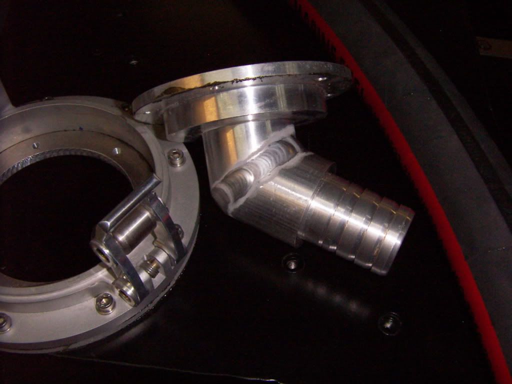
Almost finished my fuel system installation. Today i installed my FIller necks and hoses.
The RCR provided Fillerneck was modified by welding a hose adaptor ( done on my lathe) in a app 50 ° angle to it. The adaptor was sized to fit a ID 1,5" hose which is also the size of the tank filler.
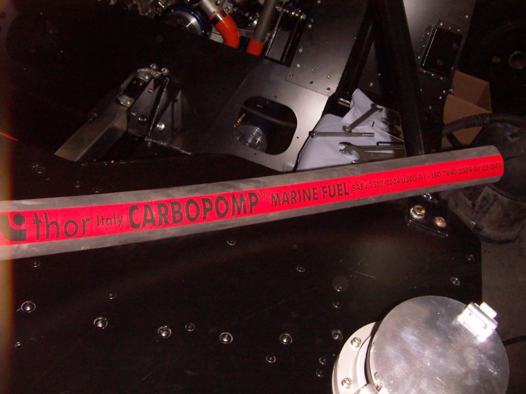
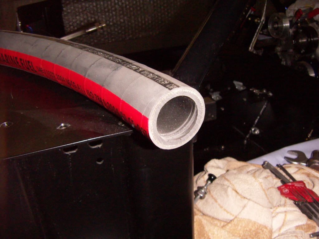
I have chosen to go with a hose between the filler neck and the tank. The hose i´m using is a very strong marine supply hose which is Lloyd´s certified and should be absolutly vapor tight. I think in a case of accident a hose is better then a pipe, because it can flex more without beeing ripped of. The hose will be fixed with 2 strong clamps per connection.
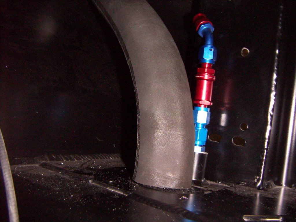
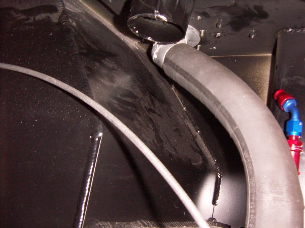
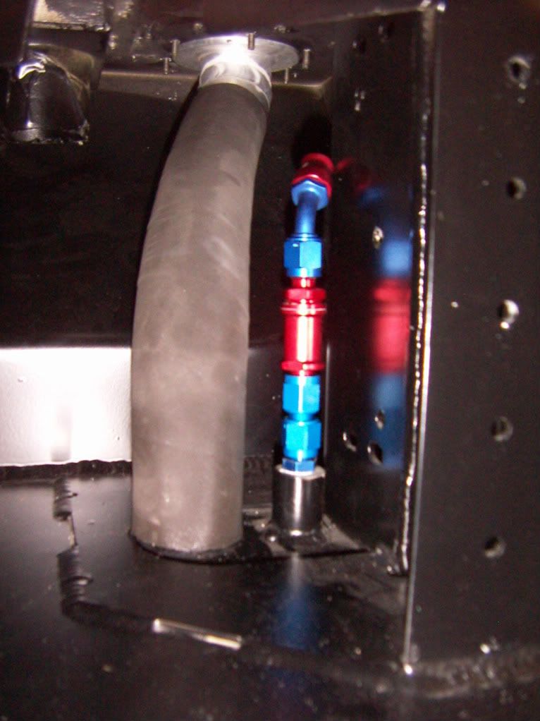
On the vent line i installed a double ball breather/rollover valve with AN Fittings using a teflon lined hose ( so hopefully no vapor diffundation either) this will be connected to another rollovervalve outside the chassis, right besides the fuel cap.
TOM
AWH: 793 h
The RCR provided Fillerneck was modified by welding a hose adaptor ( done on my lathe) in a app 50 ° angle to it. The adaptor was sized to fit a ID 1,5" hose which is also the size of the tank filler.
I have chosen to go with a hose between the filler neck and the tank. The hose i´m using is a very strong marine supply hose which is Lloyd´s certified and should be absolutly vapor tight. I think in a case of accident a hose is better then a pipe, because it can flex more without beeing ripped of. The hose will be fixed with 2 strong clamps per connection.
On the vent line i installed a double ball breather/rollover valve with AN Fittings using a teflon lined hose ( so hopefully no vapor diffundation either) this will be connected to another rollovervalve outside the chassis, right besides the fuel cap.
TOM
AWH: 793 h
Last edited:
I think in a case of accident a hose is better then a pipe, because it can flex more without beeing ripped of. The hose will be fixed with 2 strong clamps per connection.
I absolutely agree on the crashworthiness of a hose vs that of a solid connection...
Tom,
What is the source of the double ball valve. Can't seem to find any reference to it. Do you think you need to eliminate some or the fittings in the vent line. I would think they wouldn't stand up to a heavy hit. Maybe a setup similar to the main filler line. The way the picture is oriented, it looks like there isn't much room for the hose(length).
Bill
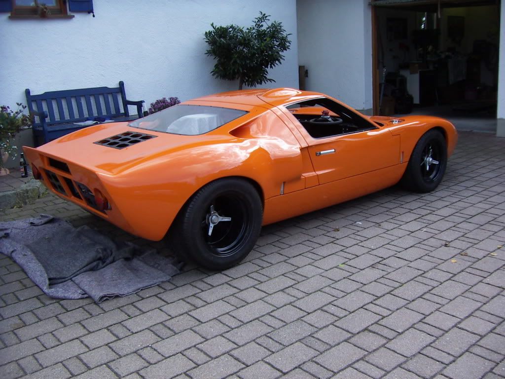
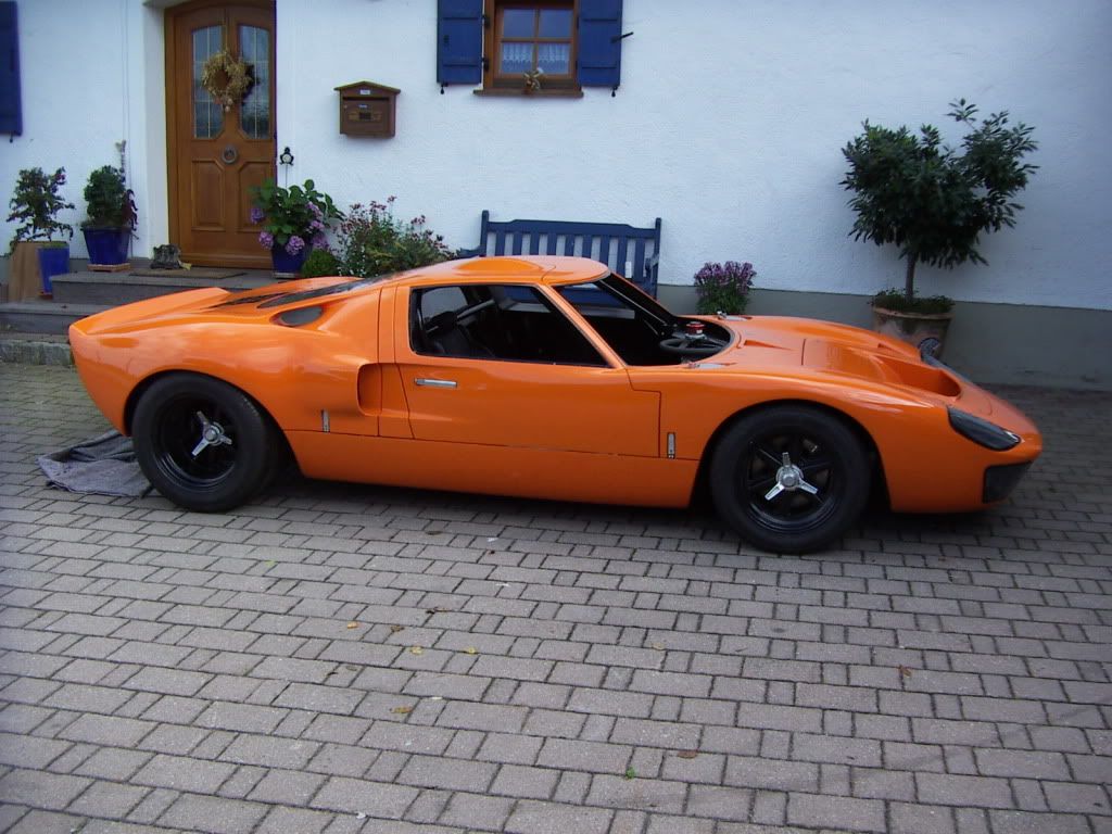
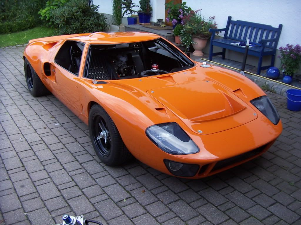
Body Reassembly
After months ( almost one year now) with just the chassis in my workshop, i´m at a stage to reinstall the body again.
I did work on a lot of small things like:
oil system filled, primed and tested.
water system almost ready to fill.
clutch working
Carb installed, accelerator pedal working
AC installed, not filled yet
Just a few small things left and the car is mechanicly finished.
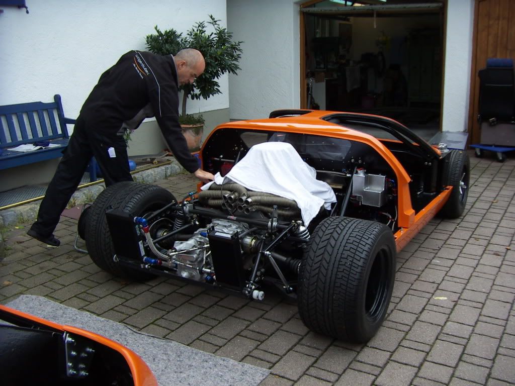
This saturday i reinstalled my bodywork with the help of Robert ( future RCr MKII owner)
All went realy well and within 6 hours the body was one and aligned again. No distortion during storage has happened to any part.
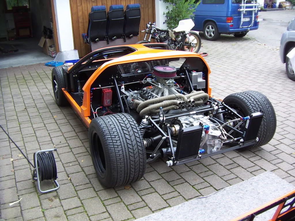
absolutely love the contrast of the black chassis to the orange colour
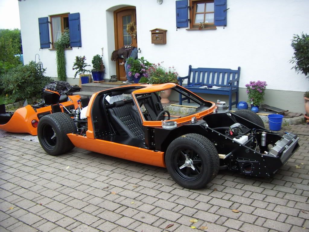
Awh: 828 h
TOM
After months ( almost one year now) with just the chassis in my workshop, i´m at a stage to reinstall the body again.
I did work on a lot of small things like:
oil system filled, primed and tested.
water system almost ready to fill.
clutch working
Carb installed, accelerator pedal working
AC installed, not filled yet
Just a few small things left and the car is mechanicly finished.
This saturday i reinstalled my bodywork with the help of Robert ( future RCr MKII owner)
All went realy well and within 6 hours the body was one and aligned again. No distortion during storage has happened to any part.
absolutely love the contrast of the black chassis to the orange colour
Awh: 828 h
TOM
That looks unbelievably cool
Love the look,plain and simple.
- Status
- Not open for further replies.
Similar threads
- Replies
- 25
- Views
- 3K