

You are using an out of date browser. It may not display this or other websites correctly.
You should upgrade or use an alternative browser.
You should upgrade or use an alternative browser.
UN1 Rebuild
- Thread starter LastPago
- Start date
Just wanted to calculate what was the impact of fitting a 0.76 ratio 5th gear instead of the original 0.82.
In a theorical world, this would allow an 8.5% increase for max speed and a 8.5% torque decrease (5th gear) wich seems to be good as the weakness of the UN1 is the primary shaft 5th gear side...no talking about the speed increase....
I post my calculations.
Cheers
Stephane
Just an observation here, but you say that having the 0.76 gear installed for 5th gear would decrease the torque thorough it, thereby preserving the weakness of the undercut shaft that 5th gear sits on. I would have thought that if you are overdriving a gear you are putting more stress on the gears and shafts as the greater ratio would give more 'power' (and harder to turn the secondary shaft) to separate the gearsets and hence want to 'bend the shafts more (since there is only 1 bearing supporting the 5th gears on the ends of the in/out shafts. Just for an example, its easier to turn the input shaft if shifted into 1st gear than it is if it was in 5th gear trying to do the same.
Hi Bruce,
Thanks for your comment. My understanding is this one :
The original wheel on the primary shaft will increase (from 39 teeth to 41).
The original wheel on the secondary shaft will decrease (from 32 teeth to 31).
This should lead to a torque decrease but I am far to be a physician and university lessons are far away behind me.:sad:
I will try to investigate more. Many thanks for your message, it may have given me a simple idea to add strength to the primary shaft. I will try if this could be possible and will post something if so.
Cheers
Stephane
Stephane,
thanks for posting all this information and pictures, I enjoy watching the progress you are making.
Not sure about your gear ratio calcs tho.
If you change from .82 to .76
then at the same car speed, you need 82/76 = 7.9% more torque at the gear input (engine is turning slower, same power, more torque), same output torque to the wheels.
If you then propose an 8.5% increase in car speed, you will need a 1.085^2 = 17.7% more output torque to the wheels, so your total increase in input shaft torque is 1.017 x1.079 = 27% more torque.
All this assuming the engine torque curve allows it.
On seeing your latest post, your spreadsheet shows 5th gear Out 39, In 32, which is the opposite of your last post (primary 39, secondary 32), so I think your reasoning was correct, but based on incorrect information with input and output swapped on your spreadsheet.
Note my ratios are slightly wrong because they are based on 0.82 and 0.76 before you wrote yoyur last post with the gear tooth numbers.
regards
Dave
Last edited:
Thanks for these contributions, it should help.
Thinking about it tonight, I think there is one important information missing : the wheels diameter. I considered that increasing teeth would mean increasing diameter, wich is not sure.
I don't already have the 0.76 gears pinions ; I am now chasing a R25 V6 gearbox to take these pinions and (maybe) adapt them to my UN1-13.
Meanwhile, I will try to refresh my mind to some, cancelled by time, formulas and calculations of torque transmission using pinions.
Many thanks to all contributors :thumbsup:
Stephane
Gentlemen,
I have been lucky enough to find a UN1-04 for very very few bucks.....30 euros :2thumbsup:....
By the way, I found a place with 4 or 5 UN1-04 sold for 225 euros per unit. If someone could be interested, I may help.
To turn back to our torque discussion :
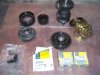
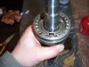
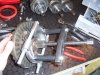
I measured the original 5th gear wheels (0.82 ratio) and the new set (0.76 ratio).
(0.82) :
Pinion (Input) : 7.6 cm, Wheel (Output) : 6.1 cm.
(0.76) :
Pinion (Input) : 7.9 cm, Wheel (Output) : 5.8 cm.
Let's remind some basic laws for calculating torque and force through wheels and pinion :
The pinion apply a force to the wheel, this makes the wheel to turn.
The force transmitted by a wheel is inversely proportional to the radius of the wheel. Plus the wheel is large, the less the force it sends is important, for a given torque.
I hope my explanations to be of sense in english....:huh:
I have been lucky enough to find a UN1-04 for very very few bucks.....30 euros :2thumbsup:....
By the way, I found a place with 4 or 5 UN1-04 sold for 225 euros per unit. If someone could be interested, I may help.
To turn back to our torque discussion :
I measured the original 5th gear wheels (0.82 ratio) and the new set (0.76 ratio).
(0.82) :
Pinion (Input) : 7.6 cm, Wheel (Output) : 6.1 cm.
(0.76) :
Pinion (Input) : 7.9 cm, Wheel (Output) : 5.8 cm.
Let's remind some basic laws for calculating torque and force through wheels and pinion :
The pinion apply a force to the wheel, this makes the wheel to turn.
The force transmitted by a wheel is inversely proportional to the radius of the wheel. Plus the wheel is large, the less the force it sends is important, for a given torque.
The force applied to the wheel produces a torque. The torque is proportional to the radius of the wheel. Apply a force to a large wheel generates more torque than if one applies the same force to a small.
Now the formulas (quite simple) :
Force applied by pinion to wheel (f)= Torque (T1) at the center of the pinion / radius of the pinion (R1).
Torque trasmitted at the center of the wheel (T2) = (f) x radius of the wheel (R2).
Let's apply these formulas to our 0.76/0.82 ratio.
For the comparison, we will use a same theorical input torque (T1) of 100.
(0.82) :
Pinion (Input) : 7.6 cm, Wheel (Output) : 6.1 cm.
R1 = 3.8 cm (7.6 cm/2), R2 = 3.05 cm (6.1 cm/2).
f (force) = T1/R1 = 100/3.8 = 26.3.
T2 (output torque) = f * R2 = 26.3 * 3.05 = 80.3.
f (force) = T1/R1 = 100/3.8 = 26.3.
T2 (output torque) = f * R2 = 26.3 * 3.05 = 80.3.
In this configuration, a given torque of 100 on pinion will generate a force of 26.3 and an output torque of 80.3 at the center of the wheel.
(0.76) :
Pinion (Input) : 7.9 cm, Wheel (Output) : 5.8 cm.
R1 = 3.95 cm (7.9 cm/2), R2 = 2.9 cm (5.8 cm/2).
f (force) = T1/R1 = 100/3.95 = 25.3.
T2 (output torque) = f * R2 = 25.3 * 2.9 = 73.4.
f (force) = T1/R1 = 100/3.95 = 25.3.
T2 (output torque) = f * R2 = 25.3 * 2.9 = 73.4.
In this configuration, a given torque of 100 on pinion will generate a force of 25.3 and an output torque of 73.4 at the center of the wheel.
0.76 set will generate less torque and force than the 0.82 set.
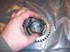
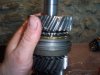
For Bruce, I also measured the 1st gear pinion and wheel to illustrate these formulas to bring you the more accurate answer.
(1st gear) :
(1st gear) :
Pinion (Input) : 3 cm, Wheel (Output) : 10.7 cm.
R1 = 1.5 cm (3cm/2), R2 = 5.35 cm (10.7 cm/2).
f (force) = T1/R1 = 100/1.5= 66.7.
T2 (output torque) = f * R2 = 66.7 * 5.35 = 356.7
f (force) = T1/R1 = 100/1.5= 66.7.
T2 (output torque) = f * R2 = 66.7 * 5.35 = 356.7
This is why, for a given torque you may apply by hand (our example of 100) to the input shaft, it is easier to make the 1st gear to turn, you hold a force of 66.7 while you only hold a force of 26.3 on the 5th gear pinion.
I hope my explanations to be of sense in english....:huh:
Cheers
Stephane
PS : I forgot tomention the legend as N or Nm. Force has to be expressed in Newtons while torque is expressed in Newton per distance : Newton per meter, Newton per centimeter.......:thumbsdown:
You are right in what you are saying, however I think you may have missed one of the points raised.
When installed in a car you need to look at it from the reverse point of view.
A car at a given speed will require a set amount of torque being applied to the wheel to maintain this speed. This is purely due to the wind resistance and other outside factors.
You need to look at the loading on the gearbox from the reverse point of view. To maintain the set amount of torque at the wheel that is required to maintain the speed, the amount of torque that the engine needs to produce will increase with a taller final drive. Therefore the torque on the particular gear set will be higher.
A very high torque motor will have its greatest affect on the taller gears, accelerating hard in top (because you can) will put much more load on the gear set than was originally designed. Most smaller engined cars tend to run out of puff, where as we are putting in engines with four or five times the amount of torque. We will have the acceleration in top gear equivalent to what they would have in second or third. Fifth gears, tend in a lot of gearboxes to be hung off the back, with bearings on one side only and may not be up to the loadings that can be applied.
Hope this helps.
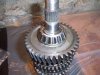
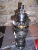
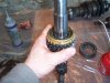
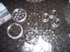
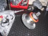
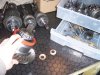
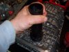
Sorry guys, I didn't had too much time to post over there, so I took some pics when rebuilding an other UN1 for friends.
Here are pics for the rebuild of primary and secondary shaft.
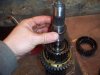
Place a new spring on the 2nd gear wheel, then place the needle bearing on the shaft. Place the 2nd gear on it, and put the syncro on the spring.
Then put the hub (be carefull ot the miss the position it was, this is why marks are usefull..). apply pressure with a press to set it on its position.
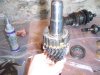
Then the locker ring and the sliding hub (same story be carefull of the side). Put a new spring on the 1st gear pinion, then the needle bearing and the 1stgear with its syncro. The picture with the syncro on the 1st gear is missing but it is exactly the same way as the 2nd gear.
Then finish with the bearing. the use of a press is necessary for this step too.
Secondary shaft, to be in position to close the side housings, is done.
Here are pics for the rebuild of primary and secondary shaft.
Place a new spring on the 2nd gear wheel, then place the needle bearing on the shaft. Place the 2nd gear on it, and put the syncro on the spring.
Then put the hub (be carefull ot the miss the position it was, this is why marks are usefull..). apply pressure with a press to set it on its position.
Then the locker ring and the sliding hub (same story be carefull of the side). Put a new spring on the 1st gear pinion, then the needle bearing and the 1stgear with its syncro. The picture with the syncro on the 1st gear is missing but it is exactly the same way as the 2nd gear.
Then finish with the bearing. the use of a press is necessary for this step too.
Secondary shaft, to be in position to close the side housings, is done.
Attachments
-
 UN 110 (Small).JPG52.5 KB · Views: 467
 -
 UN 111 (Small).JPG42.5 KB · Views: 464
 -
 UN 112 (Small).JPG48.3 KB · Views: 465
 -
 UN 113 (Small).JPG40.7 KB · Views: 461
 -
 UN 114 (Small).JPG25.9 KB · Views: 438
 -
 UN 115 (Small).JPG50.9 KB · Views: 431
 -
 UN 116 (Small).JPG48 KB · Views: 431
 -
 UN 117 (Small).JPG33.6 KB · Views: 457
 -
 UN 118 (Small).JPG60.2 KB · Views: 427
 -
 UN 119 (Small).JPG45 KB · Views: 452
 -
 UN 120 (Small).JPG33.4 KB · Views: 448
 -
 UN 121 (Small).JPG39.2 KB · Views: 457
 -
 UN 122 (Small).JPG56.3 KB · Views: 425
 -
 UN 123 (Small).JPG49.6 KB · Views: 428
 -
 UN 124 (Small).JPG35 KB · Views: 463
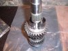
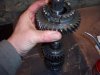
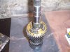
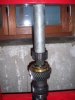
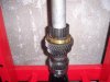
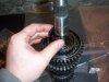
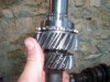
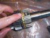
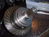
Primary shaft
Place a needle bearing then place the 3rd gear wheel on it. Put a syncro, place the hub, then the 3 rollers with their spring and slide down the slide hub.
Put a locking ring, then place above a needle bearing. Put a syncro on the 4th gear wheel and put it in place.
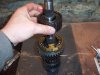
Put a washer, then the bearing (use of a press is needed).
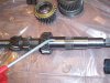
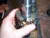
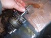
At this point the Rear bearing is missing. For this one, you have 3 alternatives. If it is not altered, you can reuse it as it is. If not you can buy a new one from Renault (approx 82 euros) or if the internal tracks are ok, just change the balls. They can be found quite easily here and you got the 20 for 10-15 euros. (PIC 145 changing balls).
Place a needle bearing then place the 3rd gear wheel on it. Put a syncro, place the hub, then the 3 rollers with their spring and slide down the slide hub.
Put a locking ring, then place above a needle bearing. Put a syncro on the 4th gear wheel and put it in place.
Put a washer, then the bearing (use of a press is needed).
At this point the Rear bearing is missing. For this one, you have 3 alternatives. If it is not altered, you can reuse it as it is. If not you can buy a new one from Renault (approx 82 euros) or if the internal tracks are ok, just change the balls. They can be found quite easily here and you got the 20 for 10-15 euros. (PIC 145 changing balls).
Attachments
-
 UN 125 (Small).JPG53 KB · Views: 424
 -
 UN 126 (Small).JPG51.4 KB · Views: 460
 -
 UN 127 (Small).JPG52.8 KB · Views: 410
 -
 UN 128 (Small).JPG56.5 KB · Views: 413
 -
 UN 129 (Small).JPG41.7 KB · Views: 444
 -
 UN 131 (Small).JPG41.3 KB · Views: 377
 -
 UN 132 (Small).JPG45.9 KB · Views: 423
 -
 UN 133 (Small).JPG39.1 KB · Views: 402
 -
 UN 134 (Small).JPG51.5 KB · Views: 435
 -
 UN 135 (Small).JPG49 KB · Views: 446
 -
 UN 145 (Small).JPG65.4 KB · Views: 463
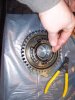
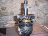
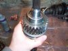
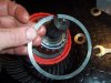
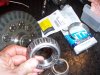
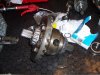
Then differential.
Unfortunately for the pics, this one was really in good shape, so I didn't have to open it.
Check for excessing moves, if so you'd have to open it and change the 3 friction washers inside. 2 are on the pic (the copper ones) and there is an other one (if i find one in a drawer I will post pic).
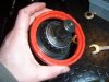
This is a UN1-13 differential, so before any move on it, remove the red crowd. Renault do not sell it any more, so it is a precious object....
The 2 differential bearings are also available outside Renault (you will save
some euros).
Remove the 2 o seal rings and the 2 bearings from both side. The use of an extractor is necessary obviously. Do not waste your time to try to get them out in good shape. Cut the cage and extract the internal. Don't throw the internal, it will be of use later (it becomes a wonderfull tool to place the new bearings under the press and also they can make a good tool 1081 (the renault tool necessary to place the differential seals).
Pic 144 differential with new bearings and new oring seals.
Cheers
Stephane
PS : I will initiate a new discussionon ways to increase UN1 strength. I searched on the forum and excluding the replacement shaft, I found nothing, but I have some cheap ideas in mind to share.
CU
Unfortunately for the pics, this one was really in good shape, so I didn't have to open it.
Check for excessing moves, if so you'd have to open it and change the 3 friction washers inside. 2 are on the pic (the copper ones) and there is an other one (if i find one in a drawer I will post pic).
This is a UN1-13 differential, so before any move on it, remove the red crowd. Renault do not sell it any more, so it is a precious object....
The 2 differential bearings are also available outside Renault (you will save
some euros).
Remove the 2 o seal rings and the 2 bearings from both side. The use of an extractor is necessary obviously. Do not waste your time to try to get them out in good shape. Cut the cage and extract the internal. Don't throw the internal, it will be of use later (it becomes a wonderfull tool to place the new bearings under the press and also they can make a good tool 1081 (the renault tool necessary to place the differential seals).
Pic 144 differential with new bearings and new oring seals.
Cheers
Stephane
PS : I will initiate a new discussionon ways to increase UN1 strength. I searched on the forum and excluding the replacement shaft, I found nothing, but I have some cheap ideas in mind to share.
CU
Attachments
-
 UN 137 (Small).JPG46.1 KB · Views: 469
 -
 UN 138 (Small).JPG44.1 KB · Views: 489
 -
 UN 139 (Small).JPG55.1 KB · Views: 496
 -
 UN 140 (Small).JPG71.1 KB · Views: 496
 -
 UN 141 (Small).JPG56.6 KB · Views: 508
 -
 UN 142 (Small).JPG59.8 KB · Views: 508
 -
 UN 143 (Small).JPG34.8 KB · Views: 466
 -
 UN 144 (Small).JPG67.5 KB · Views: 517
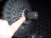
Hi Tobias,
Yes, the red crowd is for the speedometer. On Un1-13, there is no electronic sensor but a mechanical one.
Cheers
Stephane
Yes, the red crowd is for the speedometer. On Un1-13, there is no electronic sensor but a mechanical one.
Cheers
Stephane
Hi Stephan,
I am rebuilding a UN1..05 Alpine Turbo..& have to change the Diff. 180 degree..to set the backlash..I now have to shim the outer ring off the diff-bearing which are much larger than the one,s behind the inner race..do you know which model these shim,s origonally came from.
The diff. is fitted with a Quaiff.
Cheers Eddie.
Hello gentlemen,
Thanks for your comments.
Unfortunately, I am a little busy and I don't have have time to post pics and write the explanations.
Neverthless, I promise to finish the "tutorial". I will try to post pics for the differential precostraint measurements and setting the differential seals.
Skeleton, the differential bearings are standard ones, you can find them easily for an average price of 30-35 eur. The standard reference is 30209.
Keep the old ones (the center), as, as I wrote, you can use it to build a perfect tool to set the differentials seals in place : Just remove the steel lip from the center with a file, weld the part on a tube and look as it is usefull to place the seals. The tool I used on the pic attached is made this way.
Eddie, I am sorry but as my english is not that good:sad::sad::sad:, what does "shim" means:embarassed:?
Cheers
Stephane
Attachments
Carlos,
You just have to spend few bucks (50-70 euros) to buy an old "washplate machine". I don't know if the word exists in english..sorry...(this is the machine you have in your kitchen to wash plates).
It will give you this result, even more..for inside and outside.
For the finish, but it is not necessary, I have them microglass blasted. I have a little cabin to do that.
Cheers
Stephane,
The English word : shim : is the small ring or rings that are normally installed behind the inner part off the differential bearing to set the gap between the crownwheel pinion & the crownwheel....we call this : backlash : Afer turning my crownwheel through 180 degrees to get said backlash I managed to get some second-hand rings from Cris Cole in England...because now I have to move the outside ring off the bearing... & not the inside... to move the crownwheel towards the pinion... but I have another gearbox to change & I cannot find a part No. for these rings...thought you might be able to help.
Cheers Eddie.