

You are using an out of date browser. It may not display this or other websites correctly.
You should upgrade or use an alternative browser.
You should upgrade or use an alternative browser.
UN1 Rebuild
- Thread starter LastPago
- Start date

Eddie,
Sorry for the poor quality of the pic but upload limitations drove me to have the pic to be reduced.
If you want a full BMP pic, send me your email in PM.
Cheers
Stephane
Sorry for the poor quality of the pic but upload limitations drove me to have the pic to be reduced.
If you want a full BMP pic, send me your email in PM.
Cheers
Stephane
Hi Stephane,
Thanks...My friend who owns the garage where my car is specialises in Alpines..we have all the manuals..to maybe explane better... the part in the diagram is 12...on your gearbox because you don,t have to turn the diff. 180 degrees you should have the rings in the non-adustable side off the box... but ajusting the outer-ring off the bearing... it,s this part No. I need. I would need you to put up the diff. on screen from the Renault 21 turbo.
Cheers Eddie.
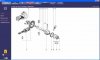
Eddie, as far as I understand, this part does not exist for the R21 differential....
Ok, so you mean a dishwasher , cool idea, even my high pressure cleaner with all the chemicals didn't achieve such a good result. Will have a look on ebay for it then ;-)
Carlos,
You just have to spend few bucks (50-70 euros) to buy an old "washplate machine". I don't know if the word exists in english..sorry...(this is the machine you have in your kitchen to wash plates).
It will give you this result, even more..for inside and outside.
For the finish, but it is not necessary, I have them microglass blasted. I have a little cabin to do that.
Cheers
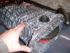
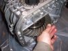
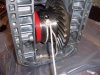
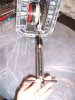
A long time, I haven't posted pics, so I sorted some pics to send a little serial to continue the thread.
Unfortunately, I have to go to prepare dinner for my kid, so comments will be posted later or tomorrow morning.:shrug:
Neverthless, I think many pics can be understood by themselves
Cheers
Stephane
Unfortunately, I have to go to prepare dinner for my kid, so comments will be posted later or tomorrow morning.:shrug:
Neverthless, I think many pics can be understood by themselves
Cheers
Stephane
Attachments
-
 UN 146 (Small).JPG48 KB · Views: 510
 -
 UN 147 (Small).JPG46.6 KB · Views: 439
 -
 UN 148 (Small).JPG56.2 KB · Views: 449
 -
 UN 149 (Small).JPG50 KB · Views: 445
 -
 UN 150 (Small).JPG34.1 KB · Views: 446
 -
 UN 151 (Small).JPG48.1 KB · Views: 484
 -
 UN 152 (Small).JPG49.8 KB · Views: 439
 -
 UN 153 (Small).JPG52.7 KB · Views: 462
 -
 UN 154 (Small).JPG45.3 KB · Views: 443
 -
 UN 155 (Small).JPG56.3 KB · Views: 489
 -
 UN 156 (Small).JPG57.1 KB · Views: 459
 -
 UN 157 (Small).JPG60.8 KB · Views: 465
 -
 UN 158 (Small).JPG50.8 KB · Views: 429
 -
 UN 159 (Small).JPG57.4 KB · Views: 510
 -
 UN 160 (Small).JPG32.6 KB · Views: 514
 -
 UN 161 (Small).JPG52.2 KB · Views: 461
 -
 UN 162 (Small).JPG49.4 KB · Views: 461
 -
 UN 163 (Small).JPG50.4 KB · Views: 450
 -
 UN 164 (Small).JPG72.8 KB · Views: 595
 -
 UN 165 (Small).JPG61.3 KB · Views: 507
 -
 UN 166 (Small).JPG57.5 KB · Views: 495
 -
 UN 167 (Small).JPG31.4 KB · Views: 419
 -
 UN 168 (Small).JPG54.1 KB · Views: 433
 -
 UN 169 (Small).JPG64.2 KB · Views: 484
 -
 UN 170 (Small).JPG41.6 KB · Views: 454
 -
 UN 171 (Small).JPG69.8 KB · Views: 555
 -
 UN 172 (Small).JPG50.3 KB · Views: 444
 -
 UN 173 (Small).JPG25.2 KB · Views: 427
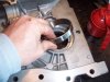
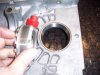
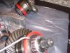
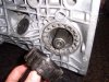
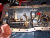
ok, here we are...
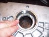
Place the differential bearing track in their respective places, then oil them(a press is necessary).
At this step, if you haven't placed the spring and the locking ball for the rear gear, it is the last time you can do it.
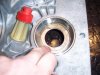
Place the lip seals in their places. You need a tool to do that that you can easily do with the center of a worn 30209 bearing (see my previous posts). The recommended height of the lip from casting is 0.5 cm.
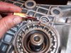
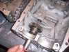
Now, as the differential bearings are new, we need to adjust the differential preload.
Put the differential in the casting without the axles and then secure all bolts with the right torque. 50 NM for the 4 10 mm bolts and 25 NM for all the other ones.
Give the differential a few turns by hand, then tie a rope to it. Using a dynamometer, measure the load. You must have a "force" of 5,5 / 6.5 KG to have the differential to turn. The pressure is setted through the "tulip" on the right side of the gearbox. Mark the position of the tulip, then unscrew it (3-4 teeth).
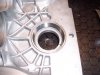
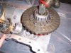
Reopen the gearbox,
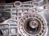
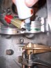
Place all axles and verify that all is working.
Place the 5th gear axle.
Remove the primary and secondary shafts.
Then the gearbox is ready for final assembly.
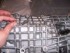
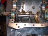
Prepare the casting for sealing with Loctite 518 (red)
I secure bearings with green loctite but it is not an obligation.
Place the primary shaft, then the secondary.
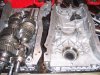
Close the gearbox paying attention that the reverse gear finger is in the right slot. It must enter the track you can see on pic UN 166 behind the pinion.
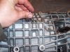
Secure all bolts in the right order with the right torque.
Then place the rear fixation plate securing bolts and using blue loctite.
To be continued
Cheers
Stephane
Place the differential bearing track in their respective places, then oil them(a press is necessary).
At this step, if you haven't placed the spring and the locking ball for the rear gear, it is the last time you can do it.
Place the lip seals in their places. You need a tool to do that that you can easily do with the center of a worn 30209 bearing (see my previous posts). The recommended height of the lip from casting is 0.5 cm.
Now, as the differential bearings are new, we need to adjust the differential preload.
Put the differential in the casting without the axles and then secure all bolts with the right torque. 50 NM for the 4 10 mm bolts and 25 NM for all the other ones.
Give the differential a few turns by hand, then tie a rope to it. Using a dynamometer, measure the load. You must have a "force" of 5,5 / 6.5 KG to have the differential to turn. The pressure is setted through the "tulip" on the right side of the gearbox. Mark the position of the tulip, then unscrew it (3-4 teeth).
Reopen the gearbox,
Place all axles and verify that all is working.
Place the 5th gear axle.
Remove the primary and secondary shafts.
Then the gearbox is ready for final assembly.
Prepare the casting for sealing with Loctite 518 (red)
I secure bearings with green loctite but it is not an obligation.
Place the primary shaft, then the secondary.
Close the gearbox paying attention that the reverse gear finger is in the right slot. It must enter the track you can see on pic UN 166 behind the pinion.
Secure all bolts in the right order with the right torque.
Then place the rear fixation plate securing bolts and using blue loctite.
To be continued
Cheers
Stephane
Guys,
Just before anyone breaks anything, a taller final drive ratio will result in a higher torque loading on the gearbox, not a lower one.
Changing from a 0.82 to a 0.76 final drive will stress the gearbox more, not less.
Think of it this way, if you decrease the engine rpm at a given speed, you must increase the torque to maintain the same speed (to maintain the same power; power being a function of torque x rpm). Therefore, to reduce the torque loading on the gearbox, you want to increase the engine rpm by using a lower final drive.
Power = Torque x RPM
At a given speed, the power output to the wheels is constant. Therefore, if you lower the engine rpm, you must increase torque and vice versa.
1074R/001,
well put, you have agreement on this from myself and Tim in posts #24 and #27, I'm sure Stephane will have thought it through by now.
Stephane, let us know how you get on with the roll pins for the output shafts. I just replaced a second broken one and, knowing that I now have plenty of drive shaft float, have turned to plan B, which is a well siliconed 5.6mm instead of the previous 6mm pin.
regards
Dave
You are right about the final torque.
Considering all these discussions we had about torque, weakness ...of the UN1, I made a search over the forum and see that there is no thread about the UN1 technicals.
I think it would be of great interest to have a technical approach of the UN1, having calculatons of all torque on every pinions, from input to wheels, to calculate the force necessary to mov a gt40, taking in consideration the usual forces such as CX, weight of the car, speed....basic newton physicals laws...
This would allow us to have a better understanding of the impacts and bounds of every modificatons or ways to improve the strength.
I have some ideas to share about a way to improve the rigidity of the 5th gear shaft in a budget.
I wil be away for few days and if such a thread is not opened at that time, I will try to open one.
Tim, I don't know of ways to remove float without having the steel hub machined with lower internal measures. If the gearbox is aligned correctly, the float won't be a problem, but if not , for sure it will broke. Even when new all these gearboxes had a float on the input shaft. I tried at the time to ask Renault why they did it this way, but I never got a real technical answer. As far as I know all UN1 have this input driveshaft float (I don't know for the Lotus one, if somebody knows, his knowledge is welcome)
BTW, the more details we could have from the lotus UN1 would be of great help. Looking at lotus forum, they say that the lotus UN1 is much more stronger than the original UN1. I would be interested to check where the differences are : having reference casting numbers for the housings, references stamped on the wheels and pinions...Renault is a big company and I don't imagine they did special productions for lotus (this is my personal conviction, I may be wrong...) as to maintain a spare inventory in conformity with their legal obligations just for few units is definitely not in the renault strategy.
Tim, I don't understand why you replaced the 6mm roll pin by a 5.6mm as the hole is for a 6mm. I think my "french understanding" of your message is not correct.
Thanks for posting
Cheers
Stephane
Stephane,
my theory is, if there is any wear in the output shaft spline, and any error in the hole position in the output shaft or the drive shaft hub, a tight roll pin could be stressed by application of torque under acceleration and some torque reversal on overrun.
Yes, the hole size is 6mm and a 6mm roll pin was very tight.
A 5.6mm roll pin with silicone sealant, will not be so tight, and this might prevent the roll pin from being stressed.
regards
Dave
Hi Dave,
Your approach is interesting.
Just a question do you use the original input shaft (I mean the shaft that goes from engine to hub) or a modified one?
I should have a solution soon to have the hub not to float anymore but I have to wait for my local CNC shop to finish my prototype.
On paper, it works...waiting for real testing.
Cheers
Stephane
Stephane,
I don't know whether my gearbox input shaft is standard or modified, as I did not build the car.
Everything I have been saying refers to the RHS gearbox output shaft to CV joint just in case I have been confusing.
Where are you trying to remove float from?
regards
Dave
I don't know whether my gearbox input shaft is standard or modified, as I did not build the car.
Everything I have been saying refers to the RHS gearbox output shaft to CV joint just in case I have been confusing.
Where are you trying to remove float from?
regards
Dave
ok Dave,
There was a misunderstanding from my side. I thought you were talking about the UN1 input shaft (It is clear that I have been reading your message too quick)
Did you tried reinforced roll pins such as those in spiral? They offer a greater resistance than the normal ones.
Cheers
Stephane
There was a misunderstanding from my side. I thought you were talking about the UN1 input shaft (It is clear that I have been reading your message too quick)
Did you tried reinforced roll pins such as those in spiral? They offer a greater resistance than the normal ones.
Cheers
Stephane
Ian Anderson
Lifetime Supporter
Hi Stephane
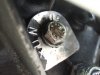
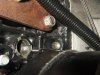
I have a UN1 in my car and have no idea on it's source
It is a UN1 09
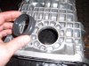
It has a speedometer pickup above the right hand drive shaft
Have you a way of saying what this box is from?
Gear ratios seem to tie in with a renault 21t box about 2850 rpm at 70mph 26inch diameter tyres.
Pics attached
thanks
Ian
I have a UN1 in my car and have no idea on it's source
It is a UN1 09
It has a speedometer pickup above the right hand drive shaft
Have you a way of saying what this box is from?
Gear ratios seem to tie in with a renault 21t box about 2850 rpm at 70mph 26inch diameter tyres.
Pics attached
thanks
Ian
Attachments
Hello Ian,
Your gearbox, if the plate is correct comes from a Renault 25 V6 (plausibles types B29E,B29F, B29G).
You should have a look at the casting year; it is, for example, stamped at the rear part of the gearbox (the housing with the arm lever). It is stamped with 2 digits ...87,88,89.....and also the revision casting digited as per X.X. If it is a 1.0 or 1.1 it is a very early one and better to chnage it for lubrification troubles. From 1.2, the lubrification scheme is ok and give also a look to the serail number of the gearbox : on the little plate sticker, the below numbers. If the number, I could read are the correct ones (14), museums will fight to have it on their shelves....;-)))
I hope this may help
Cheers
Stephane
Ian Anderson
Lifetime Supporter
Thanks Stephane
I'll have a look and see if I can find any more numbers
It is running behind an Injected Rover3.9 at about 250hp so should not "break" due to massive HP fiures
Ian
I'll have a look and see if I can find any more numbers
It is running behind an Injected Rover3.9 at about 250hp so should not "break" due to massive HP fiures
Ian