So big update. The rear mounts for the large drive units are at the welders. Was supposed to have them back this week, but he's backed up. Really wanted to show the rear motors mounted in the frame, but that will have to wait.
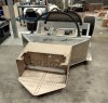
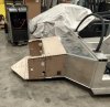
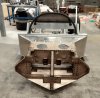
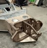
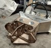
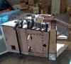
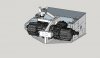
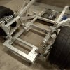
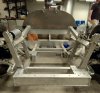
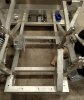
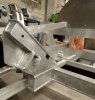
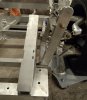
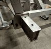
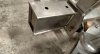
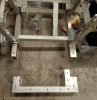
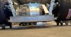
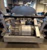
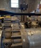
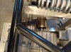
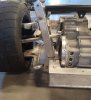
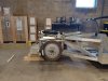
I have been working on the mounts for the two small drive units, and the pushrod suspension for the front end. My work flow is about the same as the rear mounts, draw in sketchup, laser cut in 1/4 mdf, and then final in 0.25" 6061. Slot and tab for assembly. I picked up a 150 watt laser so I can cut my own mdf, it has been a real nice addition. Turns out there are two kinds of MDF out there, light and dark colored. Get the light, I cut this first mock up out of the dark and it chars way more than the light. I think it is something to do with the iron content. Below are the pictures of where I am going for the front end. It is basically a bolt on subframe that slides over the front tub. It is exactly the same length as the existing radiator mount. Originally I was going to triangulate the center frame to the sides with 2x2 tube, but I think I am going to use I beams like I did in the center frame. There are removable I beam pieces that go horizontally from the side frame to the center, you can see them in the sketchup plan. They have to be removable for the drives to slide in. You can see the mounts from them in the MDF. The frame will hold the two small tesla drives opposed to each other. Power from each drive will be transmitted to front drive shafts via short 1:1 enclosed chain drive gear boxes. I am going to use the sprockets and chain from a Nissan GTR differential.
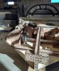
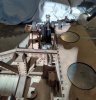
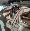
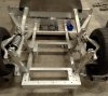
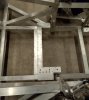
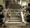
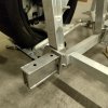
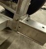
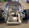
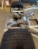
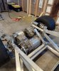
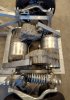
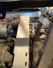
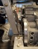
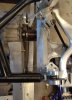
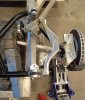
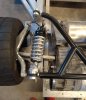
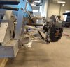
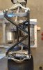
The suspension system is pretty unique. I took inspiration from the new ford GT cars that use 2 springs (torsion bar and coil spring) and a lock out mechanism so that you can run two truly different spring rates and ride heights on the car, one for street and one for track. In my setup I am using a penske 8760 for the damper, a 7/8 x 14 inch torsion bar from a sprint car for one spring, it is inside the bell crank axle, and a spring keeper from a off road truck to hold the original 8 x 2.5" coil spring. The keeper looks like it has a shock in there, but it is just a guide. Axle is held with pillow blocks that have not arrived yet, but I made MDF dummies to just get everything on the car. The pictures show the suspension in full extension. As you can see there is alot of room on the keeper for the hydraulic lift puck. I never liked how the spring is almost fully compressed on the stock system when the pucks are extended. I am going to do a custom controller for the ramliftpro, so that I can use ride height sensors, and really do custom presets. The setup gives the ability to easily swap out the torsion bar or the coil springs, without having to jack the car up, and I can run up to a 12 inch spring in the keeper. A wide variety of spring rates are available with this setup. The lockout mechanism is not shown yet, but is a short hydraulic cylinder that lifts to push the front bell crank arm, when locked out the coil spring will not be able to compress and the torsion bar rotates inside the bell crank axle. The push rod to the lower front A arm comes off at a 6.5 degree angle, sort of like the rear pushrods, and give a nice straight shot for front CV joints. Suspension movement through the bell cranks is all 1:1 ratio. You can also see a mount point on the damper bell crank for a sway bar. I may clock the reservoirs on the dampers, but everything fits and works as shown. The only issue is the bell cranks are going to come though the stock front clam, if I keep the stock from end, it will have to have bump outs like some LMP cars have, or I might do a custom from end. There is some really interesting work being done with large format 3d printers.
If the front end comes together and the suspension works as designed, I will do the same dual rate setup on the rear. I designed mount points for it into the rear motor subframe.
The spyder is going to have to be trimmed in the front to fit on the set up. I may end up mounting the spyder a little high on the body to get another inch of clearance on tires.
I just ordered a upgraded steering rack and electric steering from Hill at Agile automotive. Shout out to Scott for the connection. Hill is incredibly knowledgeable about SLC's. I spoke to him for a good 2 hours in the early design phase of the front end. Everyone should buy a steering rack and electric power assist from him, the units he has are skookum. I am going with the exact same setup Scott put together. Probably going to wait for that to come in before I cut everything out of aluminium. I am going with the x-tracker hubs front and rear. My uprights are the "gen 1" flat billet pieces, so I can just drill new mounting holes for the adapters. I am really thinking about getting a set of used z06 carbon ceramic brakes and rotors, with Z06 rims. I have a line on a lightly used full set for a killer price. Has anyone done this yet? I would like to talk to them prior to pulling the trigger.
There will be two small radiators on either side of the frame, one for each motor, and a small condensers in front of one radiator for a ev hvac unit, it will be used just for the AC. Battery and rear drive unit cooling will happen in the rear. As it stands right now there will not be cooling lines running front to back on the car. Each motor cooling system is self contained unit.
Anyway, that's it for now. Open to all suggestions and comments. I'm finishing up a really big work project and on the road, so nothing is going to happen for a month or so. I may start drawing up the battery. We will see.
Bob


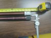
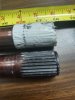
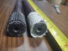
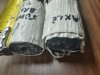
") ) 4340 chrome moly axles for a Porsche that I bought but have not used. I think they were spares for a race team NOS. If you are interested I cam measure their length & splines.
) 4340 chrome moly axles for a Porsche that I bought but have not used. I think they were spares for a race team NOS. If you are interested I cam measure their length & splines.