Hi guys,
sorry I have not been getting alerts in my email from post activity. Quick answers to some questions.
On block off plates, I have designed my own. I have only done the one for the drive itself, not the inverter. I 3d scanned the drive face, took a section and made the plate from that. I have it in nylon right now, to check fit, and it went on like a glove. I pick the tormach up next monday....the back log of parts is deep and its in there. I can share the DXF if you want it. I need to work out the inverter still. I cant decided to do one large plate that will attach over the end of the inverter "bucket" and seal both the bucket and the inverter, or do one out of aluminium and the other out of CF. That is a down the line problem for me. I am under a big push to get the rear fully done, and get the front on. The big drive issue I have right now is the 4.5:1 gear sets are "under redevelopment" by quafi, guess there has been issues. Glad I didn't buy a set, but I'm not cracking open the drives until I get a set. I have my "dry sump" lubrication system for my rear drives all spec'ed out, just need to open them up and replumb.
On batteries! Oh Batteries! The longer I wait the more options crop up. I have gone through a major rethink on them. I need a fantastic amount of amps....like 3200 peak or so at 400V. As I started to design the system getting fuses, connectors, wires, ect...that can do that peak amps, well they are not really available at realistic prices, and they just become huge. So, after a night of drinking and auguring with some EE's. A New Plan (ANP) was arrived at. We will split the pack in half, run 2x 37-40 KW, 400V 1550 max amp packs. Basically drive one large and one small drive with each pack. That way we can use all tesla fuses (the new ones are engineering works of art), tesla connectors, tesla wires, ect you get the picture. Everything, including BMS's basically get duplicated. Now there are down sides....one pack running out first being the big one, but unless I am oval tracking it, that really won't be a thing. Plus the cool thing is I could pull into charging stations an take both chargers.....which is just cool, like guys using 2 pumps to fill up lambos.
I am leaning very hard towards using high discharge 18650 cells, to make it work I need a minimum 25 Amp Peak cells, ideally 35 peak. I know these are touchy cells. I am going to be running them in immersion cooled packs, some what like Xing is doing . I have a 4 different cells that I will be building into a immersion cooled packs to test drain and cooling on. The cylinder cells have more structural integrity, and lend themselves to immersion cooling much easier. I will be doing cell level fusing like tesla. My buss plate will be different, as I am using it to seal half the cell.
Finally, the Konig motors. Yes, saw them and my read is they are axial flux motors errierly similar to a 1.5x the yasa 400 motor. they are still ~300 mm x ~300 mm thats not that small, and the cost of 2 of them with inverters is probably 70-75K min. Other problems....850V motors, 9000 max rpm. That voltage kicks you up a class of connectors, wires, fuses, ect, and isn't really compatible with the tesla stuff. If you don't want to play with 850V, and look at yasa's torque curve @ 400 V, you see peak power only 85 kw, at ~2500 rpm, and torque starts dropping right around there. you then decide to stuff 2 tesla drives up front. Hell if you are only trying to get 2x 100 kw motors upfront,, lots of good options out there. The I3 motors look real interesting. With a 9000 max rpm on the Konigs, I suspect one will only be using about 1/3 of the power range, and never see peak power. I mean really 20 inch rim wheels are only going what 1100 rpm at 100 mph or so. So unless they have some magic thin gear box on them, I think they are only going to be really helpful off the line, and not at the top end. But don't quote me on that. And you really dont need 2x 370 NM of torque in your front end off the line, there is almost no way to keep it under traction without slicks or glue paper surfaces.
There was a company that supposedly has geared axial motors ready to launch. If it happens it could really be a game changer. Still the cost will be crazy until someone start making 100K of them every 90 days, and we can grab them from the pick and pull.
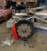
I was going to post pictures of my rear uprights with the new hubs and carbon rotors coming together, but that will have to be tomorrow. I machined them all and have everything bolted up. They look great, but somehow I bought the wrong half shafts for them.
Bob

 and keep all those CAD files.
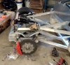
")